Hi Guy's
We are happy to announce a 2nd group buy opportunity has now opened.")
Please use the following link for more details on how you can register your interest.
The Wolverine 2nd Group buy.
We are happy to announce a 2nd group buy opportunity has now opened.
Please use the following link for more details on how you can register your interest.
The Wolverine 2nd Group buy.
Hi Guy's, @fireanimal has very kindly put his hand up, to offer completed and tested wolverine amplifier modules for those who are pushed for time or would just like their amplifier built by an experienced DiyAudio member.
A list of prices for such a service can be found in the PDF attached to the first post of the 2nd group buy thread
For those who are interested in this please advise me when you send me your excel order sheet and I'll pass your details onto @fireanimal and ensure he receives your blank boards ready for assembly.
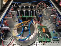
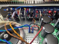
Hi Stuart. I received my boards and everything looks great. These are some from the first group buy in case anyone is wondering. I also wanted to say that I've been an EE for over 30 years and it's obvious to me the incredible amount and time and effort you guys put in to this thing. Everything from the design, to the implementation, to the BOM and user guide have been top notch. Many thanks. Gary
Crowbars work but can damage the output stage under some conditions.Hi Guy's,
Since I don’t want to fry my precious speakers, I plan to install a speaker protection like this
View attachment 1072280
I am considering also Crowbars, in order to avoid relays.
Any ideas will be highly appreciated.
There are quite a few protection designs around which use solid state relays now. I think there is an example in the wolverine build thread. I have been considering this too since I always use speaker protection.
I am afraid the circuit above does not do very much to protect your speakers, apart from disconnecting them when the amp output exceeds a certain voltage. The main destroyer of speakers is extreme DC offsets due to amp failure. The amp output being "pegged" to one of the power supply rails is not uncommon.Hi Guy's,
Since I don’t want to fry my precious speakers, I plan to install a speaker protection like this
View attachment 1072280
I am considering also Crowbars, in order to avoid relays.
Any ideas will be highly appreciated.
More advanced designs have anti thump properties for turn on and turn off, detection of DC offsets in the milli Volt range rather than Volts, and in some cases detection of amp high frequency oscillation. Forum member Bonsai at hifisonix.com offers a design using MOSFETs rather than a relay. I believe an integrated circuit used in the original design became unavailable but there is a substitute available. https://hifisonix.com/hifisonix-speaker-protection-board/
Keith
Are there any suitable output transistors from Exicon or sold by Profusion PLC that are not already on the suggested list?
Link to Profusion PLC transistor list
Link to Profusion PLC transistor list
Yes, that was @thimios testing one of the prototypes
Folks:
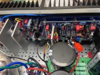
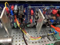
I could use some help. My Wolverine project is nearly completed and I'm at the amplifier testing stage. Something is wrong -- I'm getting 0 (or 0.1) mV across R111A and R111B on both channels, nothing more. Here is what appears to be the relevant details:
Rail voltages are +/- 48.5 VDC
Jumpers J103 is installed.
The inputs on both channels are shorted.
Pots R25, R11 and R109 are all adjusted as instructed in the Build Guide.
0.5A slow blow fuses are installed.
The amplifiers' outputs are not shorted.
Both Q104s are installed but not mounted (they're hanging loose).
D107 and D108 are the only two LEDs that are lighting (true for both channels).
I'm no engineer and have not ventured further out of concern that I'd inadvertently make matters worse. Your guidance would be greatly appreciated!
Regards,
Scott
Attachments
Thanks for your reply.Crowbars work but can damage the output stage under some conditions.
There are quite a few protection designs around which use solid state relays now. I think there is an example in the wolverine build thread. I have been considering this too since I always use speaker protection.
If crowbars ground the rails instead of the output ?
Q104 connected to wrong placeFolks:
I could use some help. My Wolverine project is nearly completed and I'm at the amplifier testing stage. Something is wrong -- I'm getting 0 (or 0.1) mV across R111A and R111B on both channels, nothing more. Here is what appears to be the relevant details:
Rail voltages are +/- 48.5 VDC
Jumpers J103 is installed.
The inputs on both channels are shorted.
Pots R25, R11 and R109 are all adjusted as instructed in the Build Guide.
0.5A slow blow fuses are installed.
The amplifiers' outputs are not shorted.
Both Q104s are installed but not mounted (they're hanging loose).
D107 and D108 are the only two LEDs that are lighting (true for both channels).
I'm no engineer and have not ventured further out of concern that I'd inadvertently make matters worse. Your guidance would be greatly appreciated!
Regards,
Scott
From the pictures it looks like there is voltage on the EF3 board but not on the IPS because those LEDS are not lit. Please confirm if you have +/-48V on the IPS.Folks:
I could use some help. My Wolverine project is nearly completed and I'm at the amplifier testing stage. Something is wrong -- I'm getting 0 (or 0.1) mV across R111A and R111B on both channels, nothing more. Here is what appears to be the relevant details:
Rail voltages are +/- 48.5 VDC
Jumpers J103 is installed.
The inputs on both channels are shorted.
Pots R25, R11 and R109 are all adjusted as instructed in the Build Guide.
0.5A slow blow fuses are installed.
The amplifiers' outputs are not shorted.
Both Q104s are installed but not mounted (they're hanging loose).
D107 and D108 are the only two LEDs that are lighting (true for both channels).
I'm no engineer and have not ventured further out of concern that I'd inadvertently make matters worse. Your guidance would be greatly appreciated!
Regards,
Scott
Jeremy
walkeris:
Hmm... now, that's interesting. There are two sets of pads for Q104. I had (foolishly) assumed that they were connected, but I have a spare set of Wolverine boards and just tested the two sets of pads for continuity. There is none. So I'll start with that correction -- thank you!
Okay, I've made that correction but still have the same problem -- still nothing between R111A and R111B.
jjs:
Where do you suggest I test?
Regards,
Scott
Attachments
jjs:
On the left channel IPS,
Connecting G1 and TP3 shows 47.9 VDC
Connecting G1 and R6 shows 41.8 VDC.
On the right channel IPS,
Connecting G1 and TP3 shows 0.78 VDC.
Connecting G1 and R6 shows 1.35 VDC.
It looks like I have at least two problems, given that the LEDs on the left channel IPS aren't lighting. Any and all suggestions are welcomed.
Thank you,
Scott
The bottom side of R6 should be negative (-48V).jjs:
On the left channel IPS,
Connecting G1 and TP3 shows 47.9 VDC
Connecting G1 and R6 shows 41.8 VDC.
On the right channel IPS,
Connecting G1 and TP3 shows 0.78 VDC.
Connecting G1 and R6 shows 1.35 VDC.
It looks like I have at least two problems, given that the LEDs on the left channel IPS aren't lighting. Any and all suggestions are welcomed.
Thank you,
Scott
Jeremy
The bottom of R6 on the schematic...The bottom side of R6 should be negative (-48V).
Jeremy
Jeremy
- Home
- Amplifiers
- Solid State
- DIYA store "Wolverine" (Son of Badger) .... suggestions ??