On that note, I thought OS was doing a lot of repairs at one time, so he probably has more experience with failed trimmers than I do. Maybe I should be the one listening...
Yes , many .. many !!
Also , yes - cheap trimmers on Japanese units fail.
Bias trimmers , they design around this by tying the wiper so the Vbe just
goes class B if it fails.
Offset - they either closely match the LTP , or use MY (sansui's) 4 diode
crude reference.
OS
In an earlier life I worked for a company that manufactured safety critical analog signal conditioning equipment (flow, temperature, pressure etc) for use in harsh hazardous environments.
We used sealed 10 and 22 turn trimmers and I don’t ever recall a pot failure being reported. Pots were typically used to trim reference voltages, zero and span (instrumentation talk for offset and gain).
If you use a good quality pot from Bourns, Spectrol (don’t even know if they’re still around) you won’t have any problems. These usually use a plastic resistive element, multiple wiper fingers and a rubber seal around the adjustment screw.
Hopefully ?? Final ....
I must say , what a pleasure to simulate.
C4a/b at 100/470p is under 10ppm. 56/270p is obscene !!
1. Keantoken's input was digested. Two pads at L1 and IPS NF can be a
shielded NFB return. This was done on some slewmasters. Just remove NF's
jumper on DIP1. Not saying that the onboard trace is very non - optimal ,
but an AP might see a couple PPM degradation.
2. Big "Audiophile" cap for C1. Parts Express anal cap is 31mm X 20mm.
All caps from 5mm LS to 30mm are a perfect fit.
3. C8 NPO ... 10mm Nichicon UKZ 47uF NPO 63V will fit.
4.Simulated D4-7 offset diodes thermally.Just mV's increase with tempco , offset
reference remains the same. I had a Sansui receiver that used this technique ,
instead of referencing off of the rails ... they used the aux. 15V supplies.
5. Keantoken pointed out my EF3 OP bias increased at full power. This
seems to be a simulation glitch in TTa/C models. MJE340 as Vbe - I get a slight
increase from 75mA to 84ma at clipping (which is 114V p-p).
6. "Helper" CM Q5 is cool. Some audiophile's put a diode at the CM ...
say it does "magic". Hmmmm .... without a servo , .2ppm at 2K. Is that
"magic" ??
LT/Sprint is attached.
OS
Attachments
OS, increase the input voltage to 2V and use Cordell's MJL3281/1302 models. You will see the bias goes crazy because the drivers and predrivers don't have enough bias current.
I don't trust OnSemi's models you are using for the MJL0281/0302. I didn't realize they were the only ones available though.
I don't trust OnSemi's models you are using for the MJL0281/0302. I didn't realize they were the only ones available though.
But on the real amps this does not happen. everything "behaves".
I'm trying to integrate real world with simulation.
Explain this ???
OS
I'm trying to integrate real world with simulation.
Explain this ???
OS
Last edited:
Hellraiser - team RED ...
First candidate for the "interface".
1. - A novel servo implementation. No signal degradation , servo controls
the CCS's ... cool 😀 . Unbalanced diamond Q1/2 , servo changes the CCS balance.
2. - Q1/2 - 3/4 thermally negate , SMD would be optimal.
3. - Performance ... "smokin' " . Slew rate - 200V/uS + .
4. - Hawksford VAS - self clamping symmetrical perfection.
This servo method will also be used on the "Spooky" , wait till you see
"Spooky V2" !! No Thimios "do a new servo issue". Refine everything
based on F 'ups type of thing ....
OS
Attachments
OS, increase the input voltage to 2V and use Cordell's MJL3281/1302 models. You will see the bias goes crazy because the drivers and predrivers don't have enough bias current.
I don't trust OnSemi's models you are using for the MJL0281/0302. I didn't realize they were the only ones available though.
Higher bias is good idea! I use 4,5mA for predrivers, and 20mA for drivers, driving 2 pairs of output devices.
Sajti
For burning power ??
On real amps and simulation R110/111 - 2.2k/220 all the way to 1k /100 has no effect.
OS
On real amps and simulation R110/111 - 2.2k/220 all the way to 1k /100 has no effect.
OS
Not really. Drivers will get just warm at 100R . Cold with 220R.
PS - had the 3 pair Sanken version of this amp , slept with it. 😀
OS
PS - had the 3 pair Sanken version of this amp , slept with it. 😀
OS
Are you able to measure the crossover point at every zero crossing? What exactly do you measure?
The problem occurs even with no load, so it occurs to me that the predrivers are struggling to drive the driver's Cob. The TO-126 predrivers can only barely drive that load at their bias current.
A 100nF capacitor across the predriver bias resistor helps them share the Cob load which is disproportionately large on the PNP side. This fixes the problem without having to increase bias current.
What is wrong with or have you considered running
Pre Drivers -> KSC3503 / KSA1381
Drivers -> MJE15032 / MJE 15033
Outputs -> MJL3281 / MJL1302
Or
Outputs -> MJL4281 / MJL4302
The 4 series seams to definitely have a higher beta and a higher FT then the MJL0281 / MJL0302
Pre Drivers -> KSC3503 / KSA1381
Drivers -> MJE15032 / MJE 15033
Outputs -> MJL3281 / MJL1302
Or
Outputs -> MJL4281 / MJL4302
The 4 series seams to definitely have a higher beta and a higher FT then the MJL0281 / MJL0302
Last edited:
What is wrong with or have you considered running
Pre Drivers -> KSC3503 / KSA1381
Drivers -> MJE15032 / MJE 15033
Outputs -> MJL3281 / MJL1302
Or
Outputs -> MJL4281 / MJL4302
The 4 series seams to definitely have a higher beta and a higher FT then the MJL0281 / MJL0302
You are looking at the Ft charts wrong. Look for Ft at 100mA. I made that mistake many times already...
I think OS is worried that normal drivers are not sufficient for 3 pairs of outputs.
You can try my Sanken models to see what quasi-saturation might look like as it affects the drivers.
Sanken 2SC3264 versus MJL3281
I think the quasi-saturation base charge currents may be exaggerated but people were pushing me to add the speed penalty of quasi-saturation because "it would be more accurate". Without actual data on it it kind of goes garbage in garbage out...
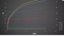
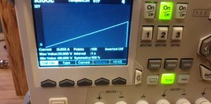
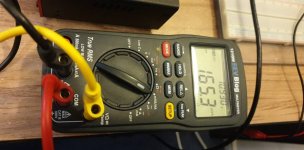
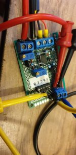
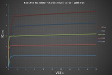
Last week I was actually fiddling around and made this transistor characteristic curve tracer and used
my power supplies ramp function so I could sweep the VCC voltage. Then I just used my DMM to record the results. I created a constant current source so I could have a fixed base current. I then put the results into Excel.
I was showing the plots to Sandro and he explained the quasi-saturation to me. I circled that area on one of the plots.
I could do the same test on some of the transistors we are looking at for this design if it would be helpful.
I will take a look at the datasheets later today to compare Ft again. Thanks for the heads up.
Yeah , I was worried
I was using something like this on mine ...
https://www.semicon.sanken-ele.co.jp/sk_content/2sa1186_ds_en.pdf
Along with 3 pair of the big MT-200's.
1.5k - R110/100R - R111
No issues.
My similar HK680 uses 2sa1837/2SC4793 , but with only 2 pair of
120W sankens.
1.5k/220R as predriver/driver Re's.
No issues here , either.
OS
- Home
- Amplifiers
- Solid State
- DIYA store "Wolverine" (Son of Badger) .... suggestions ??


