Please supply the following information as I have no heatsinks to measure.Like I said, we are not using the already existing drawing for the UMS heatsink since we are drilling new heatsinks from scratch and because of that we need the outlines
1. Name of chassis
2. Size of heatsink or heatsinks
3. Dimensions from a datum edge to an existing hole that you drill now in the x axis.
4. Dimensions from a datum edge to an existing hole that you drill now in the y axis.
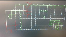
5. A basic sketch showing the other holes relieve to the datum hole so I can ensure my drawing is orientated correctly.
Attachments
Please supply the following information as I have no heatsinks to measure.
1. Name of chassis
2. Size of heatsink or heatsinks
3. Dimensions from a datum edge to an existing hole that you drill now in the x axis.
4. Dimensions from a datum edge to an existing hole that you drill now in the y axis.
5. A basic sketch showing the other holes relieve to the datum hole so I can ensure my drawing is orientated correctly.
Sure, this file should help!
stuartmp and Gianluca:
If you're going through this exercise, please map out the Wolverine hole pattern (in my case, EF3-3) for use on a 3U 400mm Dissipante chassis. I want to build a relatively compact integrated amplifier.
Thank you,
Scott
I've also adapted the UMS layout to the 3U 400 heatsinks to throw our friend Scott a bone in case you want to add the Wolverine hole pattern to this one as well @stuartmp
Attachments
Can you please consider also 4U 400 heatsinks? Caro Gianluca, vorrei usare il Dissipante 4U 400mm...Sure, this file should help!
I've also adapted the UMS layout to the 3U 400 heatsinks to throw our friend Scott a bone in case you want to add the Wolverine hole pattern to this one as well @stuartmp
")
Gaetano.
Can you please consider also 4U 400 heatsinks? Caro Gianluca, vorrei usare il Dissipante 4U 400mm...
Gaetano.
Yes, here is the file. It's the same one we use for the MonoBlock heatsinks.
Attachments
American?Well my boards arrived in today's mail already, but I haven't had a chance to get a good look at them yet
Wondering how long extra to cross into the Great White North...
Jeremy:
Your package arrived today. Your therapist would be impressed by the attention you paid to robustly packaging those boards for shipment -- they look beautiful and are completely undamaged. I can't wait to get started on the build (which will be somewhat delayed due to a few parts availability constraints)!
Many thanks!
Regards,
Scott
I'm just in the process of getting everything I need for my build as I wait for the boards, but I have a couple questions?
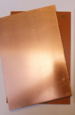
The Aluminum Plate Heatsinks - What Is the max thickness that can fit on the board, as I would like to tap the holes and not use nuts.
Inductor - I have 15awg and 17awg magnet wire on hand, can I use either, or should I order some 16awg?
Resistors - Any thoughts on using YR1 series, or just stick to the BOM.
Thanks!
I'm only seeing Rev 15 (16-04-22) in the dropbox?Build guide updated.
Revisions noted at the end of the file.
Check your Dropbox link
I have not built an amplifier, but I made my own amplifier. And when I did this, I made a template that I could for drilling the heatsink and mounting holes. I will attach the examples here. There is a drill pattern, a scale model of each of the PCBs, and a scale model of the toroids. This way I could lay out all of the components in the case ahead of time by tiling the bottom of the amp case with the patterns, and I could lay the template on the heatsink when I drilled and tapped it. The project is here
http://www.github.com/profdc9/PowerAmpAudio
in case you are interested in seeing the rest of it.
You should check the dimensions after you print with a ruler in case the printer scales it.
http://www.github.com/profdc9/PowerAmpAudio
in case you are interested in seeing the rest of it.
You should check the dimensions after you print with a ruler in case the printer scales it.
Attachments
Sorry, its updated nowI'm only seeing Rev 15 (16-04-22) in the dropbox?
What you are planning is impossible.stuartmp
hello please could you print.lay6 of 4 pairs wolverine🙏🙏
I plan to do it manually. with the thoner method and double layer ironing
You will never meet the creepage and clearance requirements. You will spend so much time on this is simply not worth it.
If by some miracle you manage to get a working board that doesn't have traces that short due to the high voltage.
Then you'll need to put hundreds of dollars of components on the boards and when its all finished you will wonder is this a good as the real thing. Please don't waste your time.
Put your name down for the next group buy.
ok, where do I write down my name, how do I sign upWhat you are planning is impossible.
You will never meet the creepage and clearance requirements. You will spend so much time on this is simply not worth it.
If by some miracle you manage to get a working board that doesn't have traces that short due to the high voltage.
Then you'll need to put hundreds of dollars of components on the boards and when its all finished you will wonder is this a good as the real thing. Please don't waste your time.
Put your name down for the next group buy.
- Home
- Amplifiers
- Solid State
- DIYA store "Wolverine" (Son of Badger) .... suggestions ??