A lot has changed in 257 pages and since 2012, not the least of which is the available parts. Is version 2.4 as noted on the store page the `latest revision' for BOM and and other revisions that applies to the store boards?
Is there a good post# that outlines current state of the art?
Would it be possible for the greater good (the greater good), for the OP to update and revise the first/original posting and append any changes or noting applicable posts where revisions are detailed?
many thanks
Is there a good post# that outlines current state of the art?
Would it be possible for the greater good (the greater good), for the OP to update and revise the first/original posting and append any changes or noting applicable posts where revisions are detailed?
many thanks

Well, so far so good. Power up with the DBT in place. No smoke.
Bit uncertain about my DMM readings per the guide:
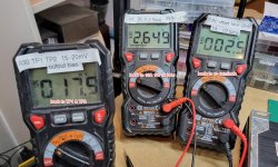
R7 target: <0.05V Mine: -2.69 DCV I couldn't get an mV reading, it showed OL ???? Leads on 10R 1W resistor.
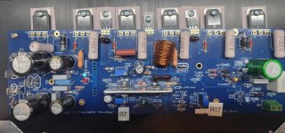
R17 target: 1mV to 2mV Mine: -017.9mV Leads on DC offset. +/-
R30 target: 15-20mV Mine: -002.5 mV Leads to TP1 & TP2 Final bias target is 44mV between TP1 & TP2
I removed the DBT and started to checked readings when I started to smell smoke and shut it all down.
Appreciated any thoughts.
Bit uncertain about my DMM readings per the guide:
R7 target: <0.05V Mine: -2.69 DCV I couldn't get an mV reading, it showed OL ???? Leads on 10R 1W resistor.
R17 target: 1mV to 2mV Mine: -017.9mV Leads on DC offset. +/-
R30 target: 15-20mV Mine: -002.5 mV Leads to TP1 & TP2 Final bias target is 44mV between TP1 & TP2
I removed the DBT and started to checked readings when I started to smell smoke and shut it all down.
Appreciated any thoughts.
Attachments
I attempted to set the R30 trimpot for maximum resistance, but likely got it reversed. If I have a trimpot attached to my DMM leads, which way is max and which min?Need to run the bias all the way down before hooking it up without DBT. the way it is now the bias is WAY high without the DBT.
I'm following your build closely Chip. I will soon be testing my boards as well.
I was also somewhat confused as to whether the proper setting of R30 would result in the trimmer being adjusted to fully clockwise, or fully counter-clockwise.
Your build looks great so far!👍
I was also somewhat confused as to whether the proper setting of R30 would result in the trimmer being adjusted to fully clockwise, or fully counter-clockwise.
Your build looks great so far!👍
The guide says to measure the voltage across R14 to set the current of R7. The voltage should be 8.25VDC.
The 10 ohm resistors are a preliminary check to insure nothing is going to draw huge amounts of current on start-up. These need to be removed before you do your final adjustment on R30 as you final bias will rise a lot.
The max of R30 will be where the resistance across it is highest (What direction you need to rotate it will change depending on how you mount the pot so it's not really relevant). Connect the ohm meter to it and turn it which ever direction makes the reading go up. You can measure this without lifting the boards from the heat sink by connecting you leads to R25 and R30 (the leads closest to the adjuster pot).
With 10R in place adjust R30 for minimum voltage reading across 10R.
If this success,power off.
Remove 10R,place fuses.
Connect voltmeter(D.C mV scale)across emitter resistor,power on,adjust the bias trimmer for the recommended bias current.
Attention,you will measure D.C voltage on emmiter resistors.
You need to calculate the current,voltage/resistor value .
Lets suppose that your voltage reading is 0.01V or 10mV depending of what meter scale used(volt or mV).That is 0.01v/0.22ohm=0.045A or 45mA.
I hope this helps.
Last edited:
Thanks for this input. in order to measure the R30 pot, I connect one lead to R25 and R30. R30 is the trimmer pot. Do you mean R35 and R29 the resistors on each side of the pot? Sorry for being dense on this, but I really want to make sure it is set correctly before firing up again.The guide says to measure the voltage across R14 to set the current of R7. The voltage should be 8.25VDC.
The 10 ohm resistors are a preliminary check to insure nothing is going to draw huge amounts of current on start-up. These need to be removed before you do your final adjustment on R30 as you final bias will rise a lot.
The max of R30 will be where the resistance across it is highest (What direction you need to rotate it will change depending on how you mount the pot so it's not really relevant). Connect the ohm meter to it and turn it which ever direction makes the reading go up. You can measure this without lifting the boards from the heat sink by connecting you leads to R25 and R30 (the leads closest to the adjuster pot).
Be sure and clip the 10R when you are finished. I left them in place and installed the fuses. The fuses will bypass the resistors until they blow, if something happens. Something did happen with mine, self-inflicted, and since it had the resistors installed, blew the fuse, then took out one of the outputs. If I had removed the resistors, pretty sure the fuse would have saved the ouput. It has MT-200 Sankens, pretty robust.
Are there corresponding resistors for R7 and R17 that I can use to check their settings? I've experimented with several guesses, but no luck.Yes, that's the resistors I was referring to.
I checked that all three pots were set correctly.
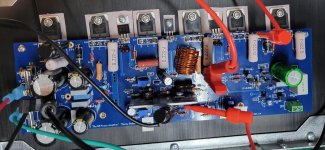
I booted up with DBT in place, still with the 10R resistors in place. Everything looked good, R30 reading was low.
I then removed the 10R resistors and put the 4A SB fuses in.
And I powered up with the DBT still in place.
This time the DBT cycled from dim to bright to dim to bright.
Not sure what would cause that.
Should I remove the DBT or is something amiss?
Attachments
- Home
- Amplifiers
- Solid State
- diyAB Amp The "Honey Badger" build thread