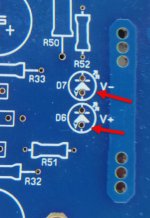
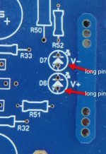

Not happen to me ...yet.The long pin isn't always anode any more. They switch them up sometimes to keep it exciting.
Then a battery and a resistor is the best tester .
Analog multimeter's red test wire is the battery minus pole,capable of confusing anyone unsuspecting.
Bleeders are nice for safety but not needed really. All the CRC resistors actually cause a saggy supply. They aren't needed for an amp with any PSSR like the Honeybadger. Snubbers are nice to have but not absolutely necessary. Standard diodes aren't as noisy as ultra-fast switching so they are likely a better choice with no snubbers.
I'm ready to test a HB amp board. I'm pretty sure I've read that it's possible to just test the IPS & VAS first, without the driver transistors installed, but I can't seem to find much to confirm that approach? ChatGPT advises against this approach. So I guess I will go ahead and install the remaining transistors.??
Now please ask ChatGPT the following question: A half bald head has 1000 hairs. How many hairs does a completely bald head have? I bet the answer will be 2000 hairs. So, what's the validity of ChatGPT answers?ChatGPT advises against this approach.
Best regards!
The amp should operate if you add a resistor in place of the output devices between the base and emitter connections. One resistor per rail would be all that is need. Likely something around 100 ohms would be good. This would be needed to make the feedback circuit complete.
Here's the construction tips from earlier in the thread. It is doable and tip C. I believe is what you're looking for. I also attached another list of tips of I have from when I built mine in 2012. Still a great amp! I know it's a long thread but it's a good idea to make the time to read through it for other changes/tips & builder experiences. There's also some other options & changes depending on parts used in this and the other HB thread.
Attachments
- Home
- Amplifiers
- Solid State
- diyAB Amp The "Honey Badger" build thread