Is idle current too high?
I just finished building two channels of the Honey Badger.
I used a dim bulb tester to bring them online slowly, one channel at a time.
On 1 channel I'm getting a reading of 0.52 volts across R54 (22 ohms)
which means 20 ma. of idle current. Is this too much?
Drop is identical on both sides of the voltage rails. (R54 and R55, v+, v-)
I'm using the parts values called out in schematic 2.5.4
New 15v zener. R19 = 15K. +60v 0 -60v rails.
Input shorted to ground, no output connected. Fuses NOT install yet.
DC offset adjusted to 0.0v
CCS adjusted by measuring 8.25 volts across R14
0.0 volts measured across TP1-2 no attempt to set bias yet.
Is idle current too high? or is it ok to install the fuses and try to set the bias?
I've checked, and double checked my work, no cold joints, no shorts...
I removed all the output transistors, they all tested OK.
Thanks
Normal procedure would be to: 1)adjust everything while on the dim bulb tester, 2) adjust bias all the way back down as far as possible, 3) remove dim bulb tester, install rail fuses, 4) adjust everything again keeping in mind it takes at least 30 minutes to normalize after each adjustment.
When you install the fuses it will become the easiest path for the current with less resisitance. I installed smaller fuses for the first set of adjustments, then the correct size fuses for the final adjustment.
When you install the fuses it will become the easiest path for the current with less resisitance. I installed smaller fuses for the first set of adjustments, then the correct size fuses for the final adjustment.
Hello Forum Members,
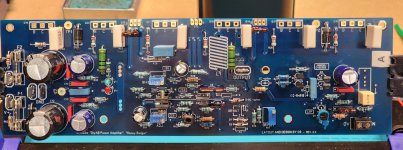
Just wanted to share my progress on the first Honey Badger board. Although the many options that are possible with this build had my head swimming at first, I am enjoying the process. I appreciate how the board is arranged in sections that are well-labeled. As a beginner this helps me understand the function of said sections.
There is work to do yet, but wanted to share my work to-date. Dave M.
Attachments
About 10 years ago I bought 1 meter 300 mm wide anodized heatsink from my old workplace. I paid 5 €  .
.
The heatsink has been sitting in a closet since then, but now I can use it in the Honey Badger build.
After a hot bath in water and drain cleaner the anodizing came off and I could put it in the wire edm to make it square after the metal band saw.
What's left is to shorten the fins from 70 mm to 40 mm, otherwise the amp will be too wide.


.The heatsink has been sitting in a closet since then, but now I can use it in the Honey Badger build.
After a hot bath in water and drain cleaner the anodizing came off and I could put it in the wire edm to make it square after the metal band saw.
What's left is to shorten the fins from 70 mm to 40 mm, otherwise the amp will be too wide.
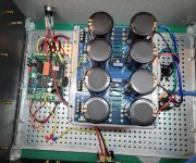
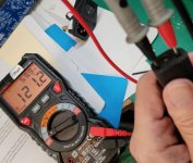
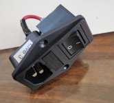
This set up using the terminal works. 120 AC V in and 64 DCV out from the PSU.I believe they are. I am so down the FW amp rabbit hole, that moving on to the HB is like learning another language. At least I understand that now.
Replaced CL-60's with 16 G wire jumpers.
I intend to put my soft start back in place without the hum. But that's tomorrow's project.
I then removed it and put the Mark J. soft start back in.
Now I am not getting more than a 1 ACV out of the IEC. Very weird. I have swapped it out for a duplicate IEC. Same result.
Not going to get very far if I can't get current into the amp. I've switched ac cords and wall outlets.
I keep checking the fuse after each attempt. Not blown.
Appreciate any ideas.
Attachments
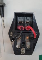
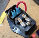
Where are you taking the AC measurement at? I see you used yellow connectors on the back of the IEC module. Do you have a good crimp there? Will the connector pull off of the wire? These are colour coded to match the wire size, you should be using blue connectors on 14 - 16 gauge wire.
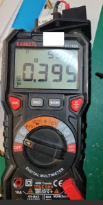
In a situation like this your ohm meter will tell you quickly where the issue is. Measure continuity between the wall end of the cord and the AC connections on the soft-start board to see which lead is open. If you find an open lead start unhooking things and testing individual components until you find the defective part. If you don't have an open lead, check to see if your meter is set right to measure AC and is actually working (plug it into your wall outlet to verify it works). Is it on the wrong range setting and possibly showing over-range? Is it mistakenly set to DC?
You have set yourself up for future hum and safety issues with the CL-60 you have installed between the supply and chassis ground. Remove that and install a proper loop breaker before you begin testing you actual amplifier boards as it's setting you up for ground loop issues.
Last edited:
See latest photos below regarding AC readings. I get 120 AC V from the AC cord I plug into the amp IEC.Where are you taking the AC measurement at? I see you used yellow connectors on the back of the IEC module. Do you have a good crimp there? Will the connector pull off of the wire? These are colour coded to match the wire size, you should be using blue connectors on 14 - 16 gauge wire.
In a situation like this your ohm meter will tell you quickly where the issue is. Measure continuity between the wall end of the cord and the AC connections on the soft-start board to see which lead is open. If you find an open lead start unhooking things and testing individual components until you find the defective part. If you don't have an open lead, check to see if your meter is set right to measure AC and is actually working (plug it into your wall outlet to verify it works). Is it on the wrong range setting and possibly showing over-range? Is it mistakenly set to DC?
You have set yourself up for future hum and safety issues with the CL-60 you have installed between the supply and chassis ground. Remove that and install a proper loop breaker before you begin testing you actual amplifier boards as it's setting you up for ground loop issues.
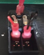
I get very small AC V reading from the IEC prongs on inside of IEC.
Fuse works.
I've done this with two different IECs.
I just built a new IEC. 14 AWG blue connectors. New fuse.
Same problem less than 1 AC V measured at prongs inside IEC.
I appreciate everyone's patience with me on this. I know it's something really simple, but it eludes me at present. ss
Attachments
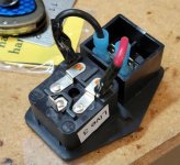
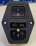
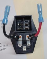
You need to check both fuses. Usually, only the line should go through the switch. In other words; Line side goes from where black wire is soldered, to the switch, then it would go to whatever is being powered. I would not take the neutral through the switch. It should go directly to what is being powered. You will need to find out which of the four contacts are normally open and which are normally closed. I would check both sets of switch contacts, probably top to bottom for continuity when switch is on and no continuity when switch is off. If this is a double pole switch, which it appears to be, you could run both the line and neutral through the switch.
That particular IEC has fuses on both the line and neutral.
That particular IEC has fuses on both the line and neutral.
And we're back. IEC sorted. Soft start back in place. Reading 63.2 DCV +/- from the PSU.
I can't say I understand what the issue (s) were that I recently encountered, but I have an increased appreciation that "everything matters - no details are too small!"
And no hum. But when I add the speaker protection, I get the hum. I will leave that aside and now, finally will start building a HB amp board.
Let the adventure continue after this 4-month detour.
I want to say thanks to everyone who walked along with me and provided the questions I didn't think of.
Very grateful for all the help.
- Home
- Amplifiers
- Solid State
- diyAB Amp The "Honey Badger" build thread