There we go. Good measurements on the resistors.
Those are crazy low voltage LEDs and/or your meter puts out a higher voltage than most. I really thought you may have had your meter set to diode check. Darn. Either way, it's not a worry per se. If your LEDs light just connected to the meter... then they may light in circuit with resistor. If you have it all soldered/stuffed properly, it's likely that they'll be BRIGHT when you have them powered through the circuit vs. through your DMM. You've likely done nothing 'wrong', but it is odd (to me).
Ben, sorry to have jumped in... thought I had it figured out re: the diode check.
Ok, I’ve searched everywhere and cant find Any discussion of this question. When attaching the transformer secondary wires to diode bridges, should the ac phase be reversed for the negative side of power supply? As I study Nelson’s power supply schematic for f5t, for example, it looks like positive side ac is hooked up to A and N, and that on negative side the secondary ac phase is reversed N and A. Does this matter? Looking at 6L6‘s various build guides, he keeps the ac secondary phases the same (for example, the Antek blue and green secondary wires attach to both bridge rectifiers on same ac terminals for positive and negative leg). Does it matter? Thanks
@Mulburg - I know you didn't ask, but you don't need a high wattage bulb to test an unloaded supply. Just a tip. 5 or 10W bulb is fine (and gives you more safety margin for your first check).
No, you don't need R9 or R10 in place for testing. They bleed the caps. It's going to take awhile for them to bleed without a load and without bleeders. So, just be aware, and either install them or manually bleed the caps as needed.
Are those measurements in ohms between different ground points? What do you mean by first and second test?
R9 and R10 are bleed resistors so that if there is no load (ie amplifier board) connected when you power off, the resistor will discharge the capacitors. However if the LED and its resistor are installed, they will bleed off the capacitors.
As for the resistance reading, what are the units of 0.568? Ohm? kOhm? Always include unit of measurement when reporting. When you have the red probe on V+ and the black probe on Ground, the measured resistance should rise as the multimeter charges the capacitors. The resistance should be much higher than 1 Ohm.
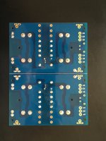
I had asked for pictures previously. A picture of the top and bottom of the board would help us help you.
As for the resistance reading, what are the units of 0.568? Ohm? kOhm? Always include unit of measurement when reporting. When you have the red probe on V+ and the black probe on Ground, the measured resistance should rise as the multimeter charges the capacitors. The resistance should be much higher than 1 Ohm.
I had asked for pictures previously. A picture of the top and bottom of the board would help us help you.
Last edited:
Thanks for that tip on the bulbs. About the same for all of them. Ben mention two places to check from unless I misunderstood.@Mulburg - I know you didn't ask, but you don't need a high wattage bulb to test an unloaded supply. Just a tip. 5 or 10W bulb is fine (and gives you more safety margin for your first check).
No, you don't need R9 or R10 in place for testing. They bleed the caps. It's going to take awhile for them to bleed without a load and without bleeders. So, just be aware, and either install them or manually bleed the caps as needed.
Are those measurements in ohms between different ground points? What do you mean by first and second test?
Gotcha. So, you did the two measurements and got 568,000 ohms and 563,000 ohms? 0.568Mohms & 0.563Mohms. Similar to what Ben said, and I had asked earlier re: the confusion with your current limiting resistor for your LED... be sure you always provide units and prefixes as appropriate. Quite a difference between <1 ohm and a few 100 kilo-ohms 
If it is MOhm, then that is good. There are no shorts.
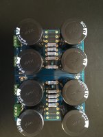
Looking at the picture, the capacitors and resistors appear to be in their correct places. I see that the bleed resistors are in place too.
Looking at the soldering, it appears to me that the copper pads at the capacitors are not fully filled with solder, and the solder joints appear rough. However I am not totally sure because it is hard to tell from the picture. A good solder joint should be smooth and shiny.
Last edited:

I have my multimeter set to auto, it defaults to mega ohms. It seems to work when I switch back and forth from a resistor, r9 for example. If I hold the probes in place, for the above tests, the values do steadily decrease.What do you mean by "M for the tests"?
I cannot see the last example wiring photo, it is missing. Could you re-post please.diyAudio Universal Power Supply Circuit Board v3 illustrated build guide. (October 2013)
(Any photo with a link directly below will go to full-size file of the photo)
This build guide will show a typical use of the diyAudio PSU v3 circuit board. This specific build will be suitable for any of the Pass/Firstwatt amps that use a +/-25V supply. If you need a higher voltage make sure you use capacitors of a suitable voltage rating for your project. You may always have a higher voltage rating, but do not use a cap with a lower voltage rating than your rails.
Useful Links
BOM - http://www.diyaudio.com/forums/images/diy/store/board-documentation/P-PSU-1V30/P-PSU-1V30-bom.xls
Schematic - http://www.diyaudio.com/forums/imag...mentation/P-PSU-1V30/P-PSU-1V30-schematic.pdf
PSU18 - My Photo Gallery
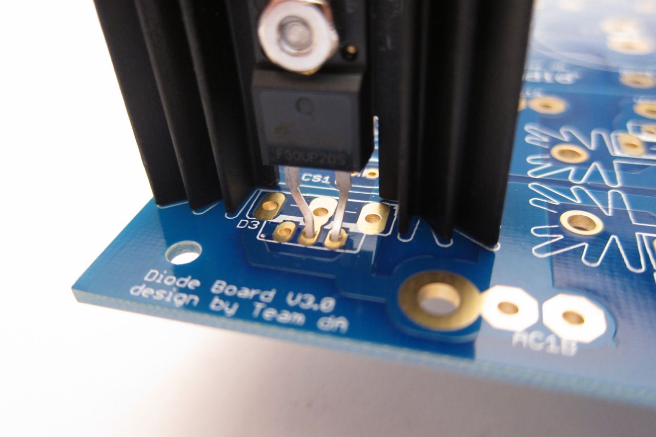
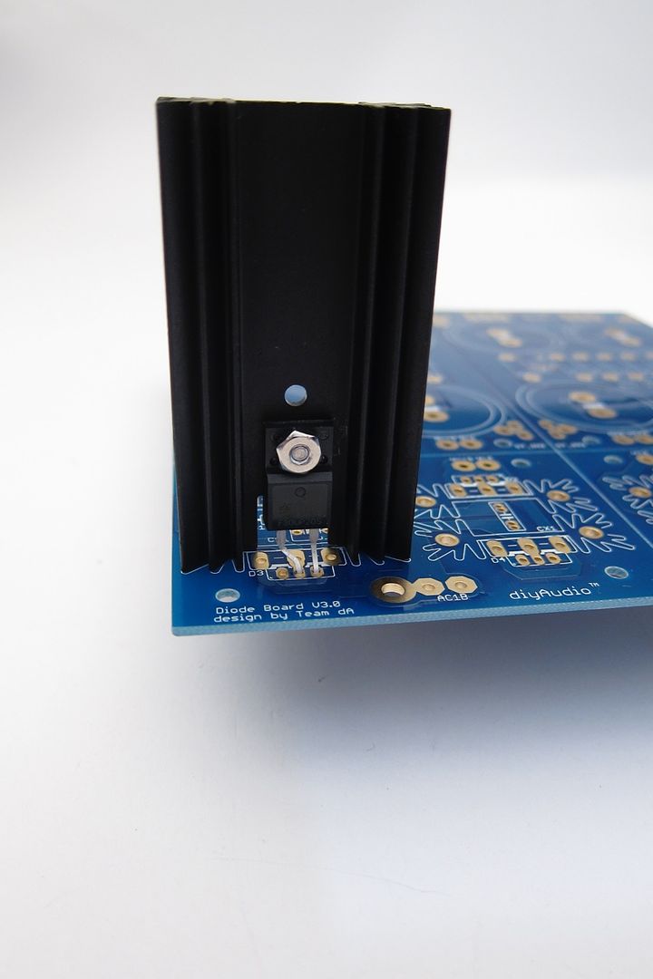
((Do not connect 2-leg TO-220 diodes as shown. See photos in 'heatsink' section.))
PSU36 - My Photo Gallery
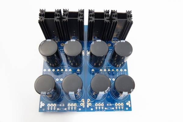
Fully stuffed
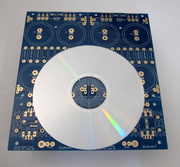
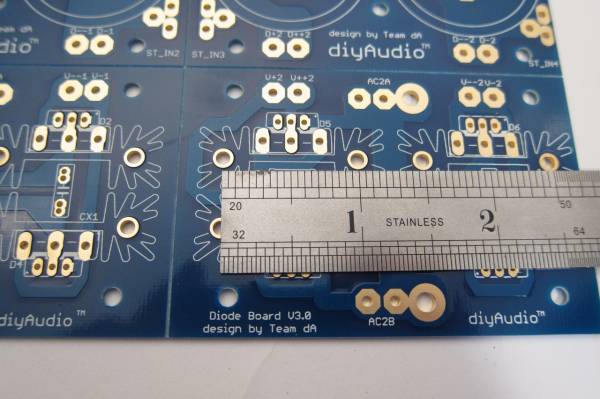
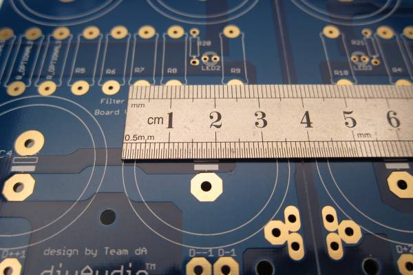
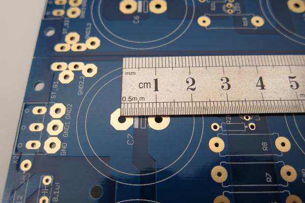
PCB scale
Dimensions -
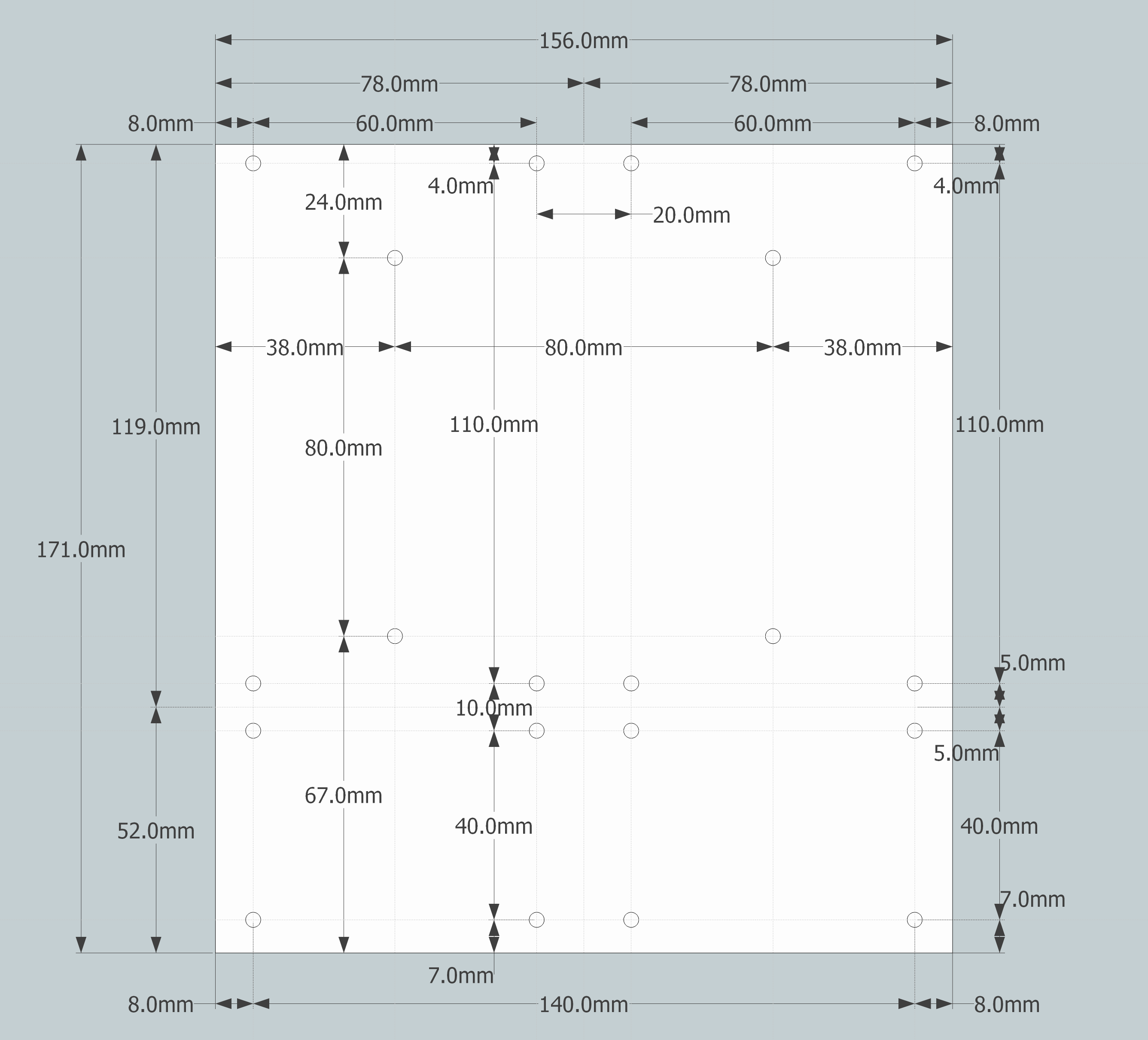
PCB dimensions

PSU14 - My Photo Gallery
The heatsinks are one inch post spacing. Look at the BOM for a specific part suggestion and find something similar that you can use. The sinks I used in this guide are of the same outer profile, so they fit the pads perfectly, but are quite a bit taller. A number of parts will be available that will work.
IMG_2134 - My Photo Gallery
This board can accept capacitors of up to 35mm diameter.
Equally important is the lead spacing - the caps should be 10mm 'snap in'. 10mm radial leads will work as well, but usually the bigger diameter caps have the 'snap in' leads.
For more information on dimensions of the specific parts, please consult the BOM for suggested parts, and cross-reference from that part's datasheet. http://www.diyaudio.com/forums/images/diy/store/board-documentation/P-PSU-1V30/P-PSU-1V30-bom.xls
Board features -
The bridge diode section of the board can utilize either TO-247/TO-3P (larger) package devices or TO-220 (smaller). If heat dissipation / heatsinking is not an issue, you could also use conventional axial-leaded diodes. (Not shown.)
IMG_2135 - My Photo Gallery
If you would like to use snubbers on the rectifier diodes you will find that there is room for them on the top of the PCB, and inside the heatsinks.
IMG_2141 - My Photo Gallery
If you don't find enough room there, or would like to try a different snubber layout, there is plenty of place to connect on the bottom of the PCB, as you will always have one of the d=sets of diode pads empty - you can only use one type of diode at a time, for example if you are using the TO-220, the TO-247 pads will be empty and you may make connections there.
IMG_2142 - My Photo Gallery
For designs that require one, there is also room for a snubber on the output. (Per rail)
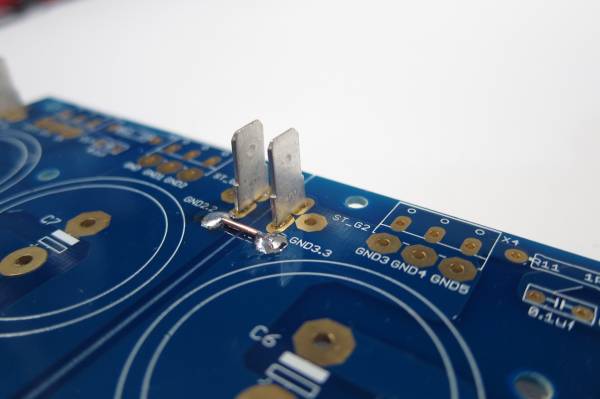
Also worth noting, in this photo you can see the multiple solder pads for the output - the row towards the edge is for the euroblock connectors, and the inner row, with the larger pads, for wire. There is also a place for a blade terminal. (Near the board edge, on the outside. To be better illustrated in a later photo.)
Building / Stuffing
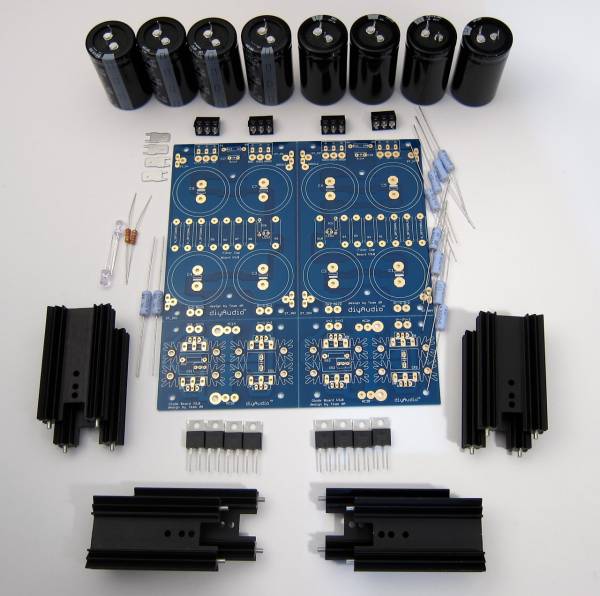
PSU41 - My Photo Gallery
This photo shows all the parts that will be used in this guide.
Starting at top and circling clockwise -
Capacitors and 'euroblock' connectors
(8) filter or 'pi' resistors
Diode heatsinks and diodes (TO-220 package shown)
(2) bleeder resistors
LED and LED resistors
AMP terminal blades
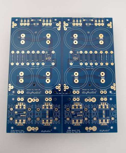
As this board has the scoring to let you separate it if you so choose, you need to notice that there is no connection from the diodes to the first capacitors nor across GND. These must be connected.
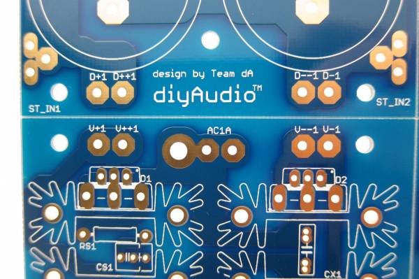
The PCB has no connection from diodes to capacitor.
The PCB also has no connection to make GND.
Since I am planning on keeping this PCB intact for the amp I am building, I need to make a connection form the diodes to the capacitor bank, and a connection to establish ground.
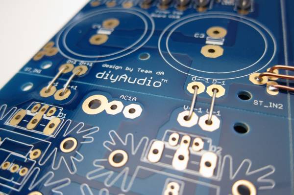
You can see all the links here (diode links not soldered in this photo)
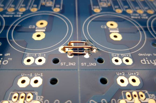
GND links. The pads on most of this PCB are all through-plated and big enough to solder from the top if you choose.
PSU28 - My Photo Gallery
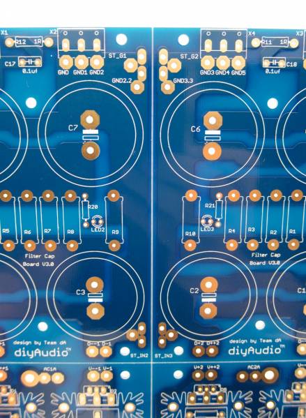
In general stuffing should be from the smaller devices to the bigger devices, so the resistors and such should be first. The filter resistors are on the outside, then the LED and LED resistors (the small brown one) and inboard are the bleeder resistors.
The silkscreen markings at the LED pads are slightly obscured, and the break in the circle, indicating where the flat of the LED should go (cathode, negative, short leg) is a little bit confusing. The legs of the LED go as shown. You can also see another link at the top of the PCB where I joined GND together.
The blades are actually taller than the euroblocks, so don't solder them first!
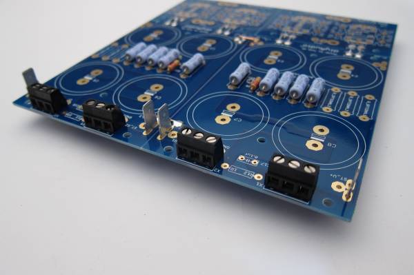
PSU27 - My Photo Gallery
The output edge shown with all the connectors in place
Capacitors -
As mentioned before, this PCB can accept caps with 10mm lead spacing and up to 35mm diameter. This photo shows 35mm caps next to 30mm. You will also commonly find some appropriate values in 25mm diameter.
PSU32 - My Photo Gallery
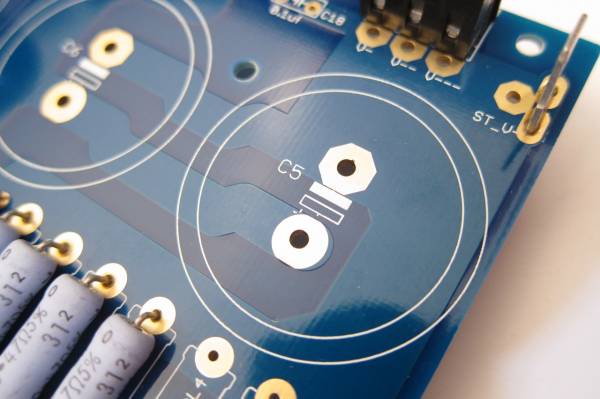
The addition of the large solder pads has obscured the markings on the PCB and the ' + ' mark is somewhat hard to make out. In each case the Positive side is marked with the open rectangle and the negative the white or filled-in rectangle. Remember that electrolytic capacitors are usually only marked on the Negative side.
PSU9 - My Photo Gallery
Note capacitor direction - you can see the negative markings on each capacitor.
Heatsinks -
The heatsinks used in this guide were chosen as they were of proper dimension to fit the PCB, and in-stock at the NOTE - I strongly suggest not separating the capacitor board if at all possible. With it intact, you can run multiple jumpers (as shown) to tie GND together and have a low-impedance, and therefore quiet GND. Splitting it will complicate making a quiet circuit. FYI.

Example wiring.
If he doesn't happen to have that exact photo to repost, the wiring is fairly straight forward. Another place that has a wonderful guide (IMO) for a FW PSU using these boards with monolithic rectifiers is linked below. They have a whole section on just the PSU. A few different parts than in this guide, but it's very close. It also shows all the wiring from mains through to the amp boards.
https://diyalephj.blogspot.com/
https://diyalephj.blogspot.com/
- Home
- Amplifiers
- Power Supplies
- diyAudio Power Supply Circuit Board v3 illustrated build guide