Bruno Putzeys never said this!
Your measurements were used in a German forum as proof for not working distortion reduction by using a resistor. As any measurements in the sound pressure domain this measurements are massively flawed by:
The distorting microphone (D2 tracks sound pressure)
Noise hiding D4 and higher
Poor equalization
I did it, I know it, been there to great length...
But you measured it. And your microphone measurements do in part show the reduction of D3 by resistor. Just as mine. See attachment.
About Brunos saying: You are right I misquoted a bit so here is the actual quote:
The following is quoted from this page as an answer to the following question.
Last question regarding the future directions you might want to explore with purifi: are you going to tackle the task of bringing transconductance/current drive amplification to the DIY and OEM market? I know your new woofer uses special trick to avoid voltage drive distortion, but having a good offering for a current drive amplifier would still be very nice for reducing distortion in "legacy" cone drivers (and maybe even for your woofer, to a lesser degree) in active filtering scenarios
Bruno Putzeys answer:
I think you are referring to the current drive used in the Kii and Grimm speakers to reduce the hysteresis distortion in the legacy drivers that are used there.
The Purifi woofer doesn’t rely on anything on the amplifier end for its performance, because we don’t want to force people to buy both drivers and electronics from us (or give the impression that we do). But neither would it make sense to give people instructions how to improve the performance of their non-Purifi drivers. Or give the impression that doing so brings them anywhere close to what our driver does. Current drive cleans up the mid-band like a treat but low frequency performance does not improve.
Besides, we sell amplifiers and drivers. If we were to start selling complete solutions, what value is there to be added by the manufacturer that buys our stuff and puts it in a box? It’s bad enough as it is with amplifier companies fearing the inevitable question “so what justifies the price of your amp compared to a DIY build”.
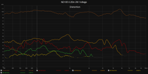
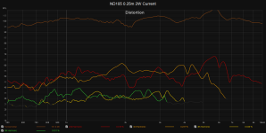
And on the distortion measurements. I have done some with normalized SPL but the result is the same so mostly I'm lazy and don't. Here is a comparison of the ND105 where the driver has higher output above 1 khz but with less odd order distortion. There is slight bump in 2nd order distortion which might be because of the higher output or might be because of the current drive. But even if it is because of the current drive I'd gladly make that trade since I find 2nd order less offensive to listen to than 3rd and especially 5th.
Attachments
What I'm really interested in is:
What's going on near my systems resonance at 47Hz?
...
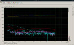
Please have a look at my measurements of D2 and D3 with microphone. The fundamental was carefully matched and equalized to be the same. The D2 does perfectly follow the sound pressure at the microphone (not in archive, sorry). The D2 is solely from the microphone.
All condenser microphones do their distortion in the D2. That is the physics of the membrane foil and the grid. It follows the distance law of condensers.
Virtually all published microphone distortion measurements over the years on the subject of distortion reduction in dynamic sound transducers have this problem.
But,
there is no masking of IMD's grassland. IMD is like a pile of colorful garbage.
What's going on near my systems resonance at 47Hz?
...
and this higher output makes your (and mine or any others) microphone distort.[...] There is slight bump in 2nd order distortion which might be because of the higher output [...]
Please have a look at my measurements of D2 and D3 with microphone. The fundamental was carefully matched and equalized to be the same. The D2 does perfectly follow the sound pressure at the microphone (not in archive, sorry). The D2 is solely from the microphone.
All condenser microphones do their distortion in the D2. That is the physics of the membrane foil and the grid. It follows the distance law of condensers.
Virtually all published microphone distortion measurements over the years on the subject of distortion reduction in dynamic sound transducers have this problem.
This is the subjectivists problem that tends to lead to silly arguments. For example about the masking of "harmonics" . The science is right on that.I find 2nd order less offensive to listen to than 3rd and especially 5th
But,
there is no masking of IMD's grassland. IMD is like a pile of colorful garbage.
You deny the basic function of the dynamic loudspeaker?Drive current distortion isn't necessarily reflected in acoustic output distortion
This is just completely wrong. And there is no way out for you of your silly argument. Not even “in certain circumstances”.in fact, it may actually be acting to reduce overall distortion in certain circumstances.
Last edited:
Driving a speaker with a hig-impedance source can definitley help to reduce distortion caused by Lvc. Likewise measuring the distortion of the voice-coil current can show distortion caused by Lvc.
But assuming that all D2 that is measured via microphone is caused by the microphone itself is plain wrong IMO.
There are other nonlinearities that also come into play.
Regards
Charles
But assuming that all D2 that is measured via microphone is caused by the microphone itself is plain wrong IMO.
There are other nonlinearities that also come into play.
Regards
Charles
No.You deny the basic function of the dynamic loudspeaker?
Suppose you have the ability to hold the cone so that it can't move. Apply an AC voltage. You'll notice drive current increase when you hold the cone, relative to a free-moving cone. This is down to the lack of the back-emf you get when the cone moves.
The increase in drive current is useful in a real-life situation, because it opposes the changes in Bl as the coil moves in the magnetic gap - in particular to the drop in Bl at the extremes.
Applying this to distortion measurements, if drive current is constant, the changes in Bl are directly reflected in terms of distortion. However, with constant drive voltage, the above mechanism will result reduced distortion - despite the fact that drive current is now distorted.
Please note, I'm not a voltage-drive (or current-drive) advocate or zealot. There are pros and cons for both (the above obviously being one favouring voltage drive). I personally am a fan of OB, and rather like the current-drive aspects of the use of a series inductor to implement the usual required EQ (which result in near-current drive at higher frequencies where excursions are small, and voltage drive at higher-excursion lower frequencies).
It seems to me that the flat SPL line (top line) is with zero ohms; the response showing the speaker reonance must be with 20 ohms. That kills the damping and therefor we see the speaker driver resonance.Looking at your measurements of the impedance, which one is the one with 20ohms in series? If i understand what you stated, the upper one. Same for distortion, rhere it appears the current driven distortion is higher, correct?
As for the distortion, I guess but it is not stated, that the lower curves are with 20 ohms?
Let me know if I am wrong.
Jan
Last edited:
It's difficult to argue with opinions when they have to be compared to measurements.[...] IMO [...]
You can find the measurements in postings #19 and #21.
There is some work happening here:
https://www.diyaudio.com/community/...urement-on-drivers.391826/page-4#post-7185358
Jan, please look at what I replied to him (>JanRSmit<) following his post you quoted.
I don't understand your post well enough to say whether you're right or not.
I tried to remember where I posted "the flat SPL line (top line)". Please, please help me.
Edit: It was in the german forum? See attachment?
Now, please, please ask again.
I don't understand your post well enough to say whether you're right or not.
I tried to remember where I posted "the flat SPL line (top line)". Please, please help me.
Edit: It was in the german forum? See attachment?
Now, please, please ask again.
@>JanRSmit<
It's not easy to read measurement diagrams. Thank you for bringing this to my attention.
When looking at my measurement diagram for many hours, a visual mnemonic has formed for me. My visual perception now sees three pairs of curves. Each pair is similar in shape. For example, the shape of D3 resembles the shape of the overlay D3o. I tried to enhance this effect with similar colors. The darker color in a pair is the overlay and thus the curve without the 20R resistor, i.e. directly on the amplifier.
Regarding my impedance plots:
Look at the Y-scale on the left of each of the two impedance diagrams. The scale shows Z in ohms. This makes it clear which diagram is which
I would like to look at your measurement a little longer before I go into it.
Attachments
Last edited:
Yes!
You are confusing speed and acceleration.
I'm not confusing anything. Driving force from the motor results in cone acceleration, which, for any given frequency, results in cone velocity, which results in cone excursion. End result is acoustic output. Back-emf from the voice-coil is proportional to velocity (which is obviously directly related to acceleration and excursion) and acts to oppose current flow.
Net result is that variations in motor efficiency are compensated for when the motor is powered by a voltage source, and since motor efficiency is proportional to Bl, then it follows that variations in Bl with excursion will have a reduced effect on acoustic output over each cycle. Hence, distortion is reduced when driven by a constant voltage source.
For low frequencies, especially around resonance, I would agree and it is also what I found in practice. For higher frequencies though, higher source impedance gives lower distortion for most of the excursion range (when excited by a lower tone in a two-tone test). The distortion starts to raise a bit earlier but also more gradually which I find to be more benign, perceptually.Net result is that variations in motor efficiency are compensated for when the motor is powered by a voltage source, and since motor efficiency is proportional to Bl, then it follows that variations in Bl with excursion will have a reduced effect on acoustic output over each cycle. Hence, distortion is reduced when driven by a constant voltage source.
In the end it is all about this: For every driver in a given acoustic situation (box type, alignment, etc) there is an optimum drive impedance vs. frequency profile which offers some 'best' overall compromise in (many kinds of) distortion and how it develops vs. level (excursion) and vs. frequency. And you can only find that by actual implementation and many test/adjust iterations because theory is quite complex and required detail data not always available, for a successful modelling/simulation.
The basic problem is that you threw up a couple of graphs without saying what it is, which are with 20 ohms, which are with 0 ohms.I don't understand your post well enough to say whether you're right or not.
I tried to remember where I posted "the flat SPL line (top line)". Please, please help me.
Jan
Well quite - that's what I've been saying. There are several sources of distortion associated with the motor - Bl modulation with excursion being a significant one when excursion is high (most relevant for low frequencies).For low frequencies, especially around resonance, I would agree and it is also what I found in practice. For higher frequencies though...
At higher frequencies current drive can be helpful, which is why I like use of a series inductor to EQ open-baffle drivers (as it increases source impedance with frequency).
[..] basic problem [...]
Dear Jan,
please stop blaming me immediately.
You found the diagram here:
https://www.diy-hifi-forum.eu/forum...on-Measurement&p=341550&viewfull=1#post341550
So please read my text on the diagram there.
(If that's even the diagram you had in your mind's eye)
Are there any unclear diagrams on this topic here on DiyAudio?
Best regards,
Bernd
Last edited:
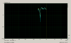
the flat SPL line (top line)
The question in the German forum was similar. This question was the reason for publishing the diagram there. I suspect that Jan Didden meant this diagram and saw it there. Now that I have published the diagram here, of course the corresponding caption is missing for you here. I would like to provide that here for you:Hornli, did the two measurements ( one with and one without the 20R resistor) produce the same SPL output from the speaker?
Look at the fundamentals at the top of the diagram. These are the frequency responses of the exciting currents for the colorful distortion diagram in Posting #1. Please ignore the (distracting) harmonics for a moment.
Overlay = yellow = without 20R (= 0R)
Green = with 20R
These are exactly the fundamentals of my colorful distortion diagram in Posting #1.
Green = with 20R was consistently “louder”.
However, I also measured experimentally with the opposite adjustment error. This adjustment error attempt did not fundamentally change the picture of the distortions.
What does holding the cone still have to do with varying BL?I'm not confusing anything. Driving force from the motor results in cone acceleration, which, for any given frequency, results in cone velocity, which results in cone excursion. End result is acoustic output. Back-emf from the voice-coil is proportional to velocity (which is obviously directly related to acceleration and excursion) and acts to oppose current flow.
Net result is that variations in motor efficiency are compensated for when the motor is powered by a voltage source, and since motor efficiency is proportional to Bl, then it follows that variations in Bl with excursion will have a reduced effect on acoustic output over each cycle. Hence, distortion is reduced when driven by a constant voltage source.
Its about the linearizing effect under voltage drive (or with even negative drive impedance). High damping means high local feedback in the driver which uses the VC as its own velocity sensor. When BL starts to drop, less than actual velocity is reported which causes more voltage accross the transfer resistance (the static VC resistance) which in turn means more current which 'kicks' the cone in the right direction almost as if the BL had been constant in the first place. This self-correcting action is frequency dependent and has phase issues, of course. The right amount of feedback will maximize the usable excursion at low frequencies. Zero drive impedance is a good starting point as most drivers have been optimized for that.What does holding the cone still have to do with varying BL?
You don't have that with current drive. BL drop directly transfers into the output.
...and it is the perfect instruction to destroy your project. The inevitable consequence is "Jump Resonance in Audio Transducers". In short: total destruction. It's bad advice here on diyAudio. You tempt the user into a destructive approach.When BL starts to drop, less than actual velocity is reported which causes more voltage accross the transfer resistance (the static VC resistance) which in turn means more current which 'kicks' the cone in the right direction almost as if the BL had been constant in the first place. This self-correcting action is frequency dependent and has phase issues, of course.
And, you know it!
It was you who first introduced "jump resonance" here on diyAudio. It was you who first linked to the paper:
https://www.researchgate.net/publication/267836914_Jump_Resonance_in_Audio_Transducers/download
What do you want to say here?
I'm not saying here that a resistor solves such problems. I only took two measurements. Once with 0R and then with 20R. Not even of what is commonly referred to as "current drive". The higher source resistance reduces all "harmonics" from nonlinear distortion by 10 dB. In the entire frequency range - including the resonance area.
Last edited:
- Home
- Loudspeakers
- Multi-Way
- Drive Current Distortion Measurement