Veleric,
In another post you said: «Goebel is the only one I ever heard that claimed that the 45 degrees was better, as far as I know. It could possibly be true for a particular shape or aspect ratio of panel, but if so, I don't think it's for the reason he claimed. In fact, he dropped the 45 degree orientation when he switched from FG skins to CF, which is evident from the images in the Goebel site you linked. People who are unfamiliar with CF may not realize this, but the diagonal lines across his CF panel are created by the weave of the CF fabric. The most common weave is a twill weave which creates such a pattern of diagonal lines while the fibers themselves are oriented at 0 and 90 degrees.»
They still use 45 degree orientation.
They are using plain weave spread tow CF, not woven twill weave.
I made one pannel with 45 degree spread tow CF on one side and 90/0 degree spread tow CF on another side. Have not tested it and yet, let me know how.
Attachments

Last edited:
Hello Lenta,Can you get this?
https://www.smooth-on.com/products/flexer-epoxy-flexibilizer/
I tried ready made flexible epoxy TG °C.
Presealed surface of the balsa, removed excess resin with cloth till the surface is dry.
I made 5 different panels with 1mm( not end grain) 280kg/m3 A4 size balsa.
What measurements you would like to see?
I have lost the thread of your testing sorry... Could you remind the type of membrane you did with the 1mm balsa? Is it with an epoxy coating or with some CF/GF cloth? I am particularly interested as I have a stock of this kind of boards (1mm x 10cm x 1m).
Christian
Hi Lenta,They still use 45 degree orientation.
They are using plain weave spread tow CF, not woven twill weave.
I think you are correct about the 45 degree orientation. My original comment was based on the first image below from the Goebel website, which looks like a twill weave with 0/90 orientation. But now I suspect that image may just be a generic carbon fiber rendering rather than a real Goebel plate. After seeing your post I went looking for other images and found the second one below from a review, and which confirms the 45 degree orientation of the carbon fiber tows.
I'll have to look at that orientation by FEA and see if I can see anything interesting. In retrospect, I'm surprised I haven't done that already.
This particular one doesn't look like a spread tow, but rather just a regular plain weave. What makes you say they use spread tow? (I'm not challenging your statement, I'm just curious) Have you seen one or a picture of one? It wouldn't shock me they did use spread tow, or offer it as an option. It offers a different look for sure that some might prefer, and might be more economical too, especially if they are using a very thin fabric, which I suspect they are.
Will answer your other questions separately.
Eric


Orientation by FEA, looking forward.
They look similar, I dont have facts.
Spread tow could be used in one layer maybe and balsa is sealed with black dye pigment underneth, so that balsa is not seen trough, smaller gaps, less resin, thinner, less weight, adjustable modulus in opposite directions.
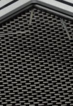
Notice in pictures tows are not symetrical.
 55g/m2 spread tow CF from Castro composites.
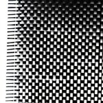
 Wowen from ECC
 Spread tow from ECC
They look similar, I dont have facts.
Spread tow could be used in one layer maybe and balsa is sealed with black dye pigment underneth, so that balsa is not seen trough, smaller gaps, less resin, thinner, less weight, adjustable modulus in opposite directions.
Notice in pictures tows are not symetrical.
55g/m2 spread tow CF from Castro composites.
Wowen from ECC
Spread tow from ECCAttachments
-
ECC-Product-Information-2018.pdf2.5 MB · Views: 58
-
 E77B56B8-AF0B-4442-8619-A6D8C859B275.png655.9 KB · Views: 56
 -
 E109391A-8AFF-4DBE-A545-3353CA5F7666.jpeg175.4 KB · Views: 59
 -
 BC4E0964-5011-4148-9BBC-9F7D77F58EF0.jpeg107.8 KB · Views: 55
 -
 5695DDDE-BC33-4056-B7C9-6F27B1AAE7F8.jpeg80.7 KB · Views: 58
Last edited:

Lenta,
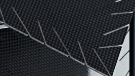
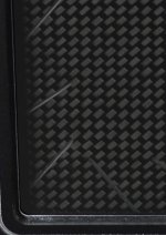
Thanks, the three images you attached showing the Goebel plates (with the slits) confirm what you said, that the fiber orientation is indeed at +/-45 degree.
It could be spread tow too. The spread tow I am familiar with has tows that are at least about 1 cm wide. But your image from ECC shows spread tow with much narrower tows (about 0.25 cm it seems). I have not seen such before.
I tried to model the 45 deg orientation in FEM but it gave exactly the same results as the 0/90. I don't believe it so I think I am doing something wrong. I will have to investigate deeper.
Thanks,
Eric
Lenta,
I now what I was wrong in the FEM, and I found one (crude) way to fix it. Am still looking for better way. Meanwhile, do you know the dimensions of the Goebel plate? I'll have to look at the patent again, maybe it's in there....
Eric
I was thingking more about it, they use asymmetric CF, so more likely 2 layers for each side. Still intentionally unbalanced, diognaly stronger than symetrical +/- 45 degree Textreme style spread tow.Lenta,
Thanks, the three images you attached showing the Goebel plates (with the slits) confirm what you said, that the fiber orientation is indeed at +/-45 degree.
It could be spread tow too. The spread tow I am familiar with has tows that are at least about 1 cm wide. But your image from ECC shows spread tow with much narrower tows (about 0.25 cm it seems). I have not seen such before.
I tried to model the 45 deg orientation in FEM but it gave exactly the same results as the 0/90. I don't believe it so I think I am doing something wrong. I will have to investigate deeper.
Thanks,
Eric
One of my 1mm plates are closer to Quasi isotropic. One layer 64kg/m2 0/90 degree, one layer 80kg/m2 +\-45 degree spread tow fabric on the other side.
How that would work in FEM.
 Triaxial, quasi isotropic carbon fiber lay up.
Last edited:
Christian,Hello Lenta,
I have lost the thread of your testing sorry... Could you remind the type of membrane you did with the 1mm balsa? Is it with an epoxy coating or with some CF/GF cloth? I am particularly interested as I have a stock of this kind of boards (1mm x 10cm x 1m).
Christian
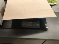
1mm x 500mm x 300mm boards I ordered were dense balsa, was suprised. 280 kg/m3 where the lightest.
Made different mebranes with 55kg/m2, 64kg/m2 and 80kg/m2 +\-45 textreme CF.
Presealed the balsa with flexible epoxy with TG 0 degree celsius.
For fabric used flexible epoxy with TG 43 degree celsius.
I will be in Munich High end show for 4 days this month and will wisit Goebel factory aswell, let me know what are you and Veleric interested to know the most.
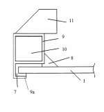
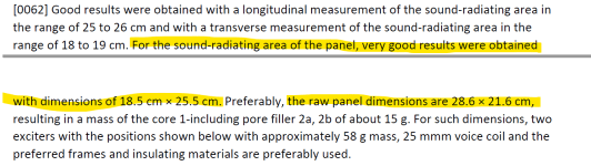
Yeah they actually mention both:28.6 cm x 21.6 cm from the Goebel patent.

My best guess is that the larger dimensions ("raw") are for the entire panel, and the smaller dimensions ("sound radiating") includes only the part inside of the foam perimeter support, or perhaps the part inside the perimeter cuts, or both.
Eric
Interesting, sound radiating area of the panel is considered 25.5 cm x 18.5 cm even if the front visible panel area is 27.5 cm x 20.5 cm.
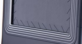
Have you considered this type of symetrical edge clamping and damping? It is most likely sorbothane, I will know when I see in person.
Have you considered this type of symetrical edge clamping and damping? It is most likely sorbothane, I will know when I see in person.
Attachments
Last edited:
Lenta,Have you considered this type of symetrical edge clamping and damping? It is most likely sorbothane, I will know when I see in person.
According to the patent, the damping material is APTK foam, which apparently is another name for EPDM foam according to this website, which I never knew before.
https://panafoamtec.de/en/cellular-rubber/
In my "anti-zylophone" testing EPDM looked very effective, while sorbothane was surprisingly poor, I thought.
Concerning the CF fabric Goebel is using, I'm not convinced that it is asymmetrical. In one image of the images you shared, it really does look asymmetric, but I wonder if it's not because of the oblique angle of the photo. In the two images below, I think it looks symmetric.
I will be in Munich High end show for 4 days this month and will wisit Goebel factory aswell, let me know what are you and Veleric interested to know the most.
That should be very interesting, I'm jealous! I will have to think about what questions you could ask. I suppose the question of the CF fabric (thickness, symmetry) and which modulus (standard, intermediate, high, ultrahigh?) would be interesting to know if they would be willing to share.
Eric


Attachments
I was able to compare by FEM a plate with 0/90 fiber orientation with +45/-45 fiber orientation. They are different, but not much. It is not at all clear to me that either would be better than the other.
For the models I used the following properties, which are based on a combination of estimates based on simple beam theory and measurements on my own balsa/CF plates:
E1,E2=14 GPa
G12=1.4 GPa
nu=0.2
pho=300 kg/m3
185 mm x 255 mm x 1.8 mm
Results below are the first 20 natural frequencies for the 0/90 orientation (first) and 45/45 orientation second. The highlighted modes are the odd, odd modes as indicated. Between the two fiber orientations, the order of the modes changes slightly, but there are no truly remarkable differences as far as I can tell. If anything, the distribution of odd,odd modes along the frequency axis seems a little better for the 0/90 case, but otherwise there is no real obvious difference from this perspective.


I wondered if the mode shapes would change with the 45/45 orientation, but if there is any difference it is too subtle for me to see. The images below show the 1,3 mode for the 0/90 (first) and 45/45 (second) as examples. Other mode shapes were equally similar.


So I don't see any obvious particular advantage of the 45/45 orientation over 0/90 based on these results. However, I think the Goebel claim was that the 45/45 orientation contributed to the damping somehow, which would not have showed up in this analysis.
Eric
For the models I used the following properties, which are based on a combination of estimates based on simple beam theory and measurements on my own balsa/CF plates:
E1,E2=14 GPa
G12=1.4 GPa
nu=0.2
pho=300 kg/m3
185 mm x 255 mm x 1.8 mm
Results below are the first 20 natural frequencies for the 0/90 orientation (first) and 45/45 orientation second. The highlighted modes are the odd, odd modes as indicated. Between the two fiber orientations, the order of the modes changes slightly, but there are no truly remarkable differences as far as I can tell. If anything, the distribution of odd,odd modes along the frequency axis seems a little better for the 0/90 case, but otherwise there is no real obvious difference from this perspective.
I wondered if the mode shapes would change with the 45/45 orientation, but if there is any difference it is too subtle for me to see. The images below show the 1,3 mode for the 0/90 (first) and 45/45 (second) as examples. Other mode shapes were equally similar.
So I don't see any obvious particular advantage of the 45/45 orientation over 0/90 based on these results. However, I think the Goebel claim was that the 45/45 orientation contributed to the damping somehow, which would not have showed up in this analysis.
Eric
Hello Lenta.I will be in Munich High end show for 4 days this month and will wisit Goebel factory aswell, let me know what are you and Veleric interested to know the most.
Thank you for the proposal.
I have in mind some topics :
- suspension (the extract from the patent answered partially). I have in mind that different materials (including metal) are used.
- the view of the impedance according to the frequency is probably a good signature of the modes, the damping of the membrane, an estimation of the inductance.
- the exciter type, location and interface to the membrane. A possible resonance on the rear side is a topic of the main thread. We could expect from a high end speaker some high BL motor and design tricks to control parasitic element like Eddy current, inductance, resonances...
As I showed in a previous post:
https://www.diyaudio.com/community/...ing-of-dml-speaker-panels.394465/post-7279558
my anti-xylophone test showed that 1/4" thick Poron 92 foam provides very good perimeter damping, particularly if the strip is over 1" wide.
So I built a new speaker using Poron foam around the perimeter to see how it would work. I disassembled a speaker build previousIy and re-used the panel. In this case the panel is a 5 mm thick 5-ply plywood, 48" long by 14" wide. I built a sturdy frame using 1.25" x 5" pine and sandwiched the Poron foam (1/4" x 1.25") between the panel and the frame around the entire perimeter of the frame (except the corners).
I think the result is my best speaker yet. Results below compare the new speaker using the Poron foam to the original speaker, which was virtually the same except instead of the Poron foam I had originally used 3M 411 double sided tape (.060" x 1/2") around the perimeter. At the time I built the original speaker, I thought that the 3M 411 was perhaps the best damping material I had available, but that was before developing my anti-xylophone test. In fact the 411 is not bad, but also not nearly as good as the Poron, according to that test.
The first plot below compares the results of a "tap test" for both versions of the speaker. In this test I tapped the plate about 2" from one end with the mic placed about the same distance from the opposite end, and about 2 mm from the plate. This test excites most of the lower natural frequecies of the panel (with the exception of the very lowest. Each peak in the response corresponds to a particular natural frequency of the panel. The result with the 3M 411 perimeter is the green line, while the brown line is for the Poron foam perimeter. As expected, the peaks at each natural frequency are much smaller with the Poron perimeter, confirming that it provides much better damping than the 3M 411 perimeter.
At the same time, it's also worth noting that while the Poron apparently does provide more effective damping, even it does come close to eliminating the modal nature of the speaker, as there are still clear peaks (resonances) in the response.

This next plot compares the frequency response (1/6 smoothing) for the two versions (Poron in green, 3M 411 in orange). The Poron version reaches a little lower in frequency, because it is softer than the 411 and hence the fundamental is lower by about 10 Hz. The Poron version also has a kind of spike at about 13K, which I can't explain. Both exhibit a dip at 120Hz, which I'm starting to think is a room effect corresponding to the ceiling height. But overall, the frequency responses of the two are about equally good.

But perhaps the most interesting difference between the two speakers is the impulse response (IR). With the 3M 411 perimeter, the IR looks like this, which is pretty typical of the DML's I've looked at.

On the other hand, the impulse IR for the Poron perimeter (below) is far cleaner. Notice, for example that the reflection at 4 ms (presumably from the floor) is evident for the Poron perimeter, but totally obscured in the ringing of the speaker with the 3M 411 perimeter.

Since I disassembled the original speaker to build the new one, I can't do side by side listening comparisons. But comparing the new one to other similar speakers I still have on hand, the new one has a much "cleaner" sound, I think.
Eric
https://www.diyaudio.com/community/...ing-of-dml-speaker-panels.394465/post-7279558
my anti-xylophone test showed that 1/4" thick Poron 92 foam provides very good perimeter damping, particularly if the strip is over 1" wide.
So I built a new speaker using Poron foam around the perimeter to see how it would work. I disassembled a speaker build previousIy and re-used the panel. In this case the panel is a 5 mm thick 5-ply plywood, 48" long by 14" wide. I built a sturdy frame using 1.25" x 5" pine and sandwiched the Poron foam (1/4" x 1.25") between the panel and the frame around the entire perimeter of the frame (except the corners).
I think the result is my best speaker yet. Results below compare the new speaker using the Poron foam to the original speaker, which was virtually the same except instead of the Poron foam I had originally used 3M 411 double sided tape (.060" x 1/2") around the perimeter. At the time I built the original speaker, I thought that the 3M 411 was perhaps the best damping material I had available, but that was before developing my anti-xylophone test. In fact the 411 is not bad, but also not nearly as good as the Poron, according to that test.
The first plot below compares the results of a "tap test" for both versions of the speaker. In this test I tapped the plate about 2" from one end with the mic placed about the same distance from the opposite end, and about 2 mm from the plate. This test excites most of the lower natural frequecies of the panel (with the exception of the very lowest. Each peak in the response corresponds to a particular natural frequency of the panel. The result with the 3M 411 perimeter is the green line, while the brown line is for the Poron foam perimeter. As expected, the peaks at each natural frequency are much smaller with the Poron perimeter, confirming that it provides much better damping than the 3M 411 perimeter.
At the same time, it's also worth noting that while the Poron apparently does provide more effective damping, even it does come close to eliminating the modal nature of the speaker, as there are still clear peaks (resonances) in the response.
This next plot compares the frequency response (1/6 smoothing) for the two versions (Poron in green, 3M 411 in orange). The Poron version reaches a little lower in frequency, because it is softer than the 411 and hence the fundamental is lower by about 10 Hz. The Poron version also has a kind of spike at about 13K, which I can't explain. Both exhibit a dip at 120Hz, which I'm starting to think is a room effect corresponding to the ceiling height. But overall, the frequency responses of the two are about equally good.
But perhaps the most interesting difference between the two speakers is the impulse response (IR). With the 3M 411 perimeter, the IR looks like this, which is pretty typical of the DML's I've looked at.
On the other hand, the impulse IR for the Poron perimeter (below) is far cleaner. Notice, for example that the reflection at 4 ms (presumably from the floor) is evident for the Poron perimeter, but totally obscured in the ringing of the speaker with the 3M 411 perimeter.
Since I disassembled the original speaker to build the new one, I can't do side by side listening comparisons. But comparing the new one to other similar speakers I still have on hand, the new one has a much "cleaner" sound, I think.
Eric
Why have they more or less abandoned the BWL plate?...
I will be in Munich High end show for 4 days this month and will wisit Goebel factory aswell, let me know what are you and Veleric interested to know the most.
//
@lentaChristian,
1mm x 500mm x 300mm boards I ordered were dense balsa, was suprised. 280 kg/m3 where the lightest.
Made different mebranes with 55kg/m2, 64kg/m2 and 80kg/m2 +\-45 textreme CF.
Presealed the balsa with flexible epoxy with TG 0 degree celsius.
For fabric used flexible epoxy with TG 43 degree celsius.
I will be in Munich High end show for 4 days this month and will wisit Goebel factory aswell, let me know what are you and Veleric interested to know the most.
How was your vist to the Munich High End show, and especially your visit at the Goebel factory? Did you learn anything new there?
Thanks,
Eric
- Home
- Loudspeakers
- Full Range
- Effect of Boundary Conditions on the Ringing of DML Speaker Panels