A rarely asked question, in the near future. I hope to live to see it ;')if the software is capable
No need to wait; it exists now. We have it at work, but it is for an extremely expensive (6+ figures) random vibration test system.
I do not know if REW has this capability but essentially without getting into all of the heavy math the transfer function is essentially the comparison of the response to the input. Or put another way, it is the function of how the input is 'transferred' to the response, hence the name.
EDIT: Well look here is a method for REW.
OK I'll stop here so I don't derail the thread. But it boils down to being potentially a quick way to calculate damping using REW.
Last edited:
I used to work with those. One had some HP computer driving a big Unholtz-Dickie amp; where I noticed a BNC signal input. I mentioned to the tech; "You should let me bring in my bass guitar and plug it in there". He said he'd do it. Never did. 20kW bass guitar amp!We have it at work, but it is for an extremely expensive (6+ figures) random vibration test system.
Probably would have needed to connect the table to some panel with bigger area, to get it to make sound.
The next place I worked at was more restrictive; I didnt ask. They would've got mad. You get one chance in all life, to do such a thing.
Ha ours is the same brand, and I have had the same thought as far as using it as a speaker amp. I joked that if one put a cone and a baffle on the front and hit the right resonant frequency it could bring down the building. It is loud enough with just the coil moving and requires ear plugs when the higher power levels are run. I have seen 20kW of power during runs as well, and even tripped the power breakers a few times.
Ever gander at how one of those tables you bolt the product onto is designed? Pretty non-resonant structure I would say. I bet something could be learned, replicated in wood at a smaller scale. They'd put the feedback accel right on the table's top; guess all locations on it move in exactly the same way, regardless of frequency.
One of the last corporations I worked for made a big blunder at the management level concerning one of those machines. Driver assembly was maybe 4-5ft in diameter; this was not a light thing. Decided to rip it out and ship it to China; install at a facility there. Forgot the caveat that China doesnt accept "used" goods as an import, so sat in customs at $1000/day for maybe 6 mos, while mgmt figured out what to do.
Shipped it back, reinstalled it in the same spot. Up there with the 3 elevators they installed taking at least a year, that we all had to listen to banging and grinding during work hours. Must've been some contract fulfillment. Never got a single ride in one before they closed the place, and eventually demo'd the whole building to make way for the next corporate structure, a little bit different.
Yeah they are enormous devices. For us, in some cases the 'slip table' is used which is a large plate of aluminum (say 8'x8'x2") bolted to the armature (speaker coil so to speak). It slides on a thin layer of oil sitting on top of a granite plate. The plate is only used in-plane so it is extremely stiff and is almost always a lot heavier than the test article.
In other cases the armature is rotated vertically and the test article is bolted to it directly, no slip table.
In all cases there is a control accelerometer attached as close as possible to where the test article attaches to the armature/table. This provides feedback to the control system to make sure the actual profile is what you specify; it is closed-loop feedback essentially.
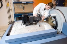
This will give an idea of the size of these things for those who have not seen them. They come in large, and larger. Images from Unholtz. The second one is an entire spacecraft sitting on top of the armature/coil assembly (the huge grey cylinder on the floor). The shakers are used to simulate rocket launches which are really hard on the spacecraft and instruments; in most cases it is the #1 thing that drives design strength and stiffness.
In other cases the armature is rotated vertically and the test article is bolted to it directly, no slip table.
In all cases there is a control accelerometer attached as close as possible to where the test article attaches to the armature/table. This provides feedback to the control system to make sure the actual profile is what you specify; it is closed-loop feedback essentially.
This will give an idea of the size of these things for those who have not seen them. They come in large, and larger. Images from Unholtz. The second one is an entire spacecraft sitting on top of the armature/coil assembly (the huge grey cylinder on the floor). The shakers are used to simulate rocket launches which are really hard on the spacecraft and instruments; in most cases it is the #1 thing that drives design strength and stiffness.
Attachments
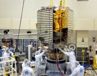
The bit that the satellite is sitting on; we had both the round and square top versions. I'd forgotten about the ship table! Even though I'd helped unbolt one at least once.
Those were interesting structures, from the POV that you could see the engineering to make them non-resonant. Push on a small area, translate that to a big area where motion is the same anywhere on its surface. Could that thinking be applied - somehow - to a DML design?

Looking on-line, I see they still - even with all that bracing - have a specified resonance and an upper limit on the frequency they can be used. After which I assume they go modal where - despite the structure - different locations on the surface begin moving differently; like a drum head does. Isnt physics wonderful?
If you happen to have a drum and a strobe light at home, the two can show what happens regarding different parts of a surface moving differently; it's pretty interesting to literally see. I'm quite sure the technique could apply as well to a sheet of foam core, plastic cardboard, or wood, suspended in a frame, excited by a driver. You'll see it go through different modes, over excitation frequencies. Too bad it'd be tough to show on a video, with an excitation frequency, as strobe frequency and a camera frame rate all different.
What those modes have to do with how it sounds, good or bad, I know nada.
What suppression of those modes via whatever bracing structure one can engineer does to the sound, I also know nada. One might assume...and one might be dead wrong too.
What that observational technique might lend toward evaluating edge termination efforts, I also know nada.
With the bright LEDs available in any flashlight these days, a FET and a function generator, I bet one could make a strobe that goes past 20kHz easily.
Those were interesting structures, from the POV that you could see the engineering to make them non-resonant. Push on a small area, translate that to a big area where motion is the same anywhere on its surface. Could that thinking be applied - somehow - to a DML design?
Looking on-line, I see they still - even with all that bracing - have a specified resonance and an upper limit on the frequency they can be used. After which I assume they go modal where - despite the structure - different locations on the surface begin moving differently; like a drum head does. Isnt physics wonderful?
If you happen to have a drum and a strobe light at home, the two can show what happens regarding different parts of a surface moving differently; it's pretty interesting to literally see. I'm quite sure the technique could apply as well to a sheet of foam core, plastic cardboard, or wood, suspended in a frame, excited by a driver. You'll see it go through different modes, over excitation frequencies. Too bad it'd be tough to show on a video, with an excitation frequency, as strobe frequency and a camera frame rate all different.
What those modes have to do with how it sounds, good or bad, I know nada.
What suppression of those modes via whatever bracing structure one can engineer does to the sound, I also know nada. One might assume...and one might be dead wrong too.
What that observational technique might lend toward evaluating edge termination efforts, I also know nada.
With the bright LEDs available in any flashlight these days, a FET and a function generator, I bet one could make a strobe that goes past 20kHz easily.
Last edited:

Thanks for the paper Deude. I am most familiar with the phase angle (tan delta) approach, which comes from my time using Dynamic Mechanical Analysis of polymeric materials (rather than engineering structures), to investigate their glass transition temperature(s) and molecular structures. I am vaguely familiar with the half power method but didn't know the details.More details in the attached paper.
Since my simple FEA program doesn't allow the incorporation of damping, putting a numerical value on the damping hasn't been a priority of mine. So far I've been satisfied to visually compare the sharpness of the peaks for a qualitative assessment of the damping of various boundary "candidates". But if Paul and Christian master the modelling, having good numbers for damping will be more important.
One possible complication of applying the half power method to my dampophone measurements is that my "y axis" is not directly displacement, but rather SPL from a close placed mic. I'm not sure if that response is linearly related to displacement or not. Is it?
Eric
That is a good question on linearity. I will think on it.
Speaking of modeling, though I normally use ANSYS, I use Fusion 360 for personal items like this. I looked into modeling plates in the simulation part of the app but it only does tetrahedron (tet) elements and not shells. That's not great. Either the model will be inaccurate or the computation times will be LONG. So I will need to find another way.
Also, sorry for the digression. It seems when I get to speaking about work I find it hard to stop!
Oh yeah agreed on the damping. When modeling for deflection it is critical that number is correct since it has a direct and large effect. We always discuss damping coefficients during design and test reviews. 'What is your Q?" is a common question.
AND THEN there is still the whole question about how much damping is optimal from a psychoacoustics perspective. Either there are some great research based models out there and/or it might end up being subjective; the latter would result in 'sounds too lively' or 'sounds too dead' kinds of assessments, like metal vs silk dome tweeters.
AND THEN there is still the whole question about how much damping is optimal from a psychoacoustics perspective. Either there are some great research based models out there and/or it might end up being subjective; the latter would result in 'sounds too lively' or 'sounds too dead' kinds of assessments, like metal vs silk dome tweeters.
Last edited:
Has anyone looked at MLV (mass loaded vinyl a.k.a. Dyanamat) as an edge damping material? It's behavior is going to be more on the cantilever supported side since it is not as bendable as foam tape. But generally speaking it is a heavy damper. It is so pliable it practically behaves like a non-Newtonian fluid.
I looked and did not see it, so pardon me if it was mentioned in this thread already.
I looked and did not see it, so pardon me if it was mentioned in this thread already.
Does it act like a dilatant or is it thixotropic?it practically behaves like a non-Newtonian fluid.
I'm assuming one would want a heavier damping at lower frequencies.
Do you, or anyone else here, know if Solidworks of any use for this kind of modeling? I have attempted one or two plate simulations, but not having good knowledge of the product my results were a bit meh.Speaking of modeling, though I normally use ANSYS, I use Fusion 360 for personal items like this.
Good question. The stuff in the photos is Noico 80mil butyl (not asphalt) I bought years ago before they exorbitantly raised the price. Noico does not have any spectral information on their web site nor can I find any independent test results.Does it act like a dilatant or is it thixotropic?
I'm assuming one would want a heavier damping at lower frequencies.
It could be due to the basic approach that Solidworks uses by default. If it was using tetrahedron (tet) elements, those work for thick objects but not so much for membranes. For thin objects you want to use shell or plate elements; the results will be more accurate and the computational time drops considerably. I do not know if Solidworks (COSMOS?) has shells but I would expect that it would.Do you, or anyone else here, know if Solidworks of any use for this kind of modeling? I have attempted one or two plate simulations, but not having good knowledge of the product my results were a bit meh.
If you have to use tets, a rule of thumb is to use second order or higher ones, and have three layers of tets through the thickness of the plate. However this will create a LOT of nodes and the solution time will go up exponentially, especially with adaptive elements.
Regardless, you want to do multiple runs while increasing either the order of your elements and/or the number of elements. Continue to do this until the last run and the current run agree within your convergence percentage. For example if you want your calculated frequencies to be within 5% then keep iterating until last and current agree within 5%.
That is all standard numerical methods stuff and is generally the same whether using Solidworks or Ansys or Nastran or whatever; they all use the same underlying numerical methods.
Last edited:
OK so I am about to start fabrication on a really large panel. More info here...
Before I do, I can set up a deflection test to measure the Young's modulus of the 3mm hardwood ply I will be using. The idea would be to provide that information here for input into the various models which would then be used to predict the behavior of the design. That predicted response at the very least could be compared against the final result, or used to alter the design before fabrication (if there is a clear indication that alteration is a good idea).
I would model the system myself with FEA but do not have access to Ansys for personal use (professional ethics). The FEA software I do have, Fusion 360, is very limited and I don't expect it to be effective.
What do y'all think?
So reading though some of the patents and papers I saw one where baffle damping was used in place of (or at least to augment) edge damping effects. Basically the idea is to have a significant acoustic absorber behind the DML panel such that resonances are damped out by virtue of pressure coupling. One of the builders here mentioned using damping material behind the DML panel and had favorable results with response smoothing IIRC.
This is less direct than edge damping, but interesting none the less and could make for an interesting experiment. Has anyone modeled this?
This is less direct than edge damping, but interesting none the less and could make for an interesting experiment. Has anyone modeled this?
I'm wondering if anyone's tried memory foam as as damping material?I had an idea to get the most out of damping materials.
To extract energy from the panel, a damping material layered under the panel has to be distorted, or squished if you will. The more it's distorted, the more energy can be extracted. But damping materials are firm, more or less, and dont really distort very much, particularly with a lightweight panel required for dml. So you end up changing the response of the panel, and extracting more energy at higher frequencies than you might want.
So the basic idea is just to allow the damping material a maximum degree of flex instead of layering it as part of a clamped or simple support.
There are several options, the simplest being to support the panel by joining it to the baffle with a strip of damping material across a gap, either as a membrane or as a rolled edge, instead of layering behind. Similarly if the damping material is thick and soft, support the panel with a layer between the panel edge and the baffle edge, again to maximise strain on the damping material.
Very soft, slow rebound
Or Butyl mastic rather than tape. Skins but stays somewhat gooey inside.
Last edited:
Sorry I missed this post until know. I would have replied earlier otherwise. I don't have any experience with Fusion 360, so I can't speak to that. To be of any use, it needs to have a modal analysis capability. Shell elements are also ideal, especially if they are of the Mindlin (thick plate) type. The ability to handle orthotropic materials is also ideal, as most panel materials are orthotropic.I would model the system myself with FEA but do not have access to Ansys for personal use (professional ethics). The FEA software I do have, Fusion 360, is very limited and I don't expect it to be effective.
What do y'all think?
Are you sure you can't use your Ansys? Does your license only allow work uses, or is it company policy? I would never encourage you to abuse the license or break your company's policies, but if I were your boss, I'd be happy for you to master new skills and features of a tool. Who knows when that skill will be useful for your company?
In any event, using whatever tool you have, as long as it has modal analysis capability, is worth playing with. It may not give you perfect results (nothing will), but it will give you a good idea of how size and shape and boundary conditions influence the natural frequencies of a panel.
Eric
Can you get this?Thanks Lenta,
I just called West Systems, but they don't have a flexibilizer for their system. I did find another epoxy supplier (local) that does, but I've never used their epoxy before. Maybe I'll give it a try, though. If you do any measurements comparing panels with and without flexibilizer, I would be very interested in the results.
Wow, 6.5 mm balsa! That must be a really stiff panel. With CF skins I am only using 1.6 mm balsa.
Eric
https://www.smooth-on.com/products/flexer-epoxy-flexibilizer/
I tried ready made flexible epoxy TG °C.
Presealed surface of the balsa, removed excess resin with cloth till the surface is dry.
I made 5 different panels with 1mm( not end grain) 280kg/m3 A4 size balsa.
What measurements you would like to see?
- Home
- Loudspeakers
- Full Range
- Effect of Boundary Conditions on the Ringing of DML Speaker Panels