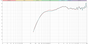
For a crossover design you will need to measure it together with the woofer anyway, so you'll see. Mic distance can also be a factor.I think the DI is very smooth. It is, however, a bit lower than expected. That would force me to crossover a bit lower, right?
Overall, the shape of the FR is strange from the beginning but I always attributed that to the driver. Maybe it's something else in your setup. Do you use any passive protection filter?
Now you know how difficult it is to measure the acoustic side thoroughly. I wouldn't be bothered by small reflections from the stand etc. - once you know there are no other major reflections, it's easy and safe to smooth that out.
Regarding filtering out distinct reflections, I have often wondered about what would be the effect taking the impulse response data is Matlab and replacing the portion of the reflected signal in the impulse response with an equivalent duration of "cleaner" waveform from somewhere after the main impulse. Or even about just replacing that part with zeros. 😀
The more scientific way to probably try and get rid of the reflection artefact is to use a proper deconvolution algorithm/adaptive filter. The general idea is to invert that comb filtering caused by the reflection that acts on the actual waveform. But all of these would distort the data to varying extents and I have never tried out any of this.. 🙂
The more scientific way to probably try and get rid of the reflection artefact is to use a proper deconvolution algorithm/adaptive filter. The general idea is to invert that comb filtering caused by the reflection that acts on the actual waveform. But all of these would distort the data to varying extents and I have never tried out any of this.. 🙂
Regarding filtering out distinct reflections, I have often wondered about what would be the effect taking the impulse response data is Matlab and replacing the portion of the reflected signal in the impulse response with an equivalent duration of "cleaner" waveform from somewhere after the main impulse. Or even about just replacing that part with zeros.
I exported the impulse response to a .txt file in REW. I imported it into Octave (Matlab clone) and windowed it similarly as REW does. Then I use the very advanced technique of just eye-balling it and repeating the last sample before the obvious reflection until the obvious reflection was over.
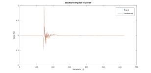
The blue original shows a reflection around sample # 375.
Then I fft-ed the impulse response to get the frequency response:
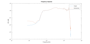
There is quite a difference in the low frequencies that doesn't matter to me. Zooming in on the portion 6-10kHz shows this:
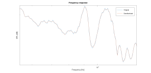
Here the dereflectivied signal is looking a bit smoother. I think it looks better. But it might be that 'the wish is the father of the thought' (dutch saying).
You're more than welcome in the Netherlands; it's only halfway across the world. It could have been twice as far!Sine sweeps are very good at rejecting noise but trying to troubleshoot someone else's measurement setup is hard through a forum.
I can provide the raw measurements if that helps. I value your help and that of others highly.
There should be no need of magic, your raw measurements of the waveguide look strange to me though, the DI and normalized directivity is as expected but everything else looks quite odd. Waveguides of that type should peak towards the lower end and fall to high frequencies without correction.
Overall, the shape of the FR is strange from the beginning but I always attributed that to the driver. Maybe it's something else in your setup. Do you use any passive protection filter?
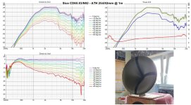
I guess you mean you expect something like this:
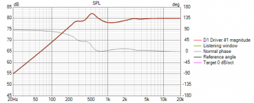
I do use a passive protection filter of two simple 100uF electrolytics soldered back-to-back. I traced the CD impedance in VituixCAD and used that together with a 50uF capacitor to simulate the sound level:
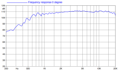
And here is the CD response as provided by Faital:
I have no EQ-ing on my minidsp.
Does that take away your concerns? Does it explain what you are seeing? Or am I missing what you guys find weird in the FR?
To be sure that the filter does what it's supposed to, it's always best to measure the actual voltage (as FR) on the driver's terminals. And use that as a correction to the measured data. I used to use a protection filter (RC) as well but stopped as it meant more trouble than a possible benefit. For reasonable SPL there's no need to use it.
Actually you have, as this is another way how to measure what the filter does 🙂
- Then, I don't know how is this possible. There must be an explanation though. Anyway, it's important to know what's the real behaviour. I would have doubts.
- Then, I don't know how is this possible. There must be an explanation though. Anyway, it's important to know what's the real behaviour. I would have doubts.
I measured my (measurement) amp when I was building a tube amp. I don't remember any weird frequency responses. The measurement without capacitor (post #347) was done with a DAC without any dsp posibilities.
I did find this FR of a CD very similar to mine (https://audioxpress.com/article/Tes...ession-drivers-coupled-with-LTH102-60-50-horn):
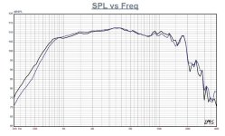
That was measured with quite a different waveguide (Faital LTH102):
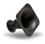
Can the CD be 'corrected' for a waveguide efficiency? Or is that very depedent on the waveguide shape? Any ideas how to determine what is going on? I don't have any CD's laying around...
I did find this FR of a CD very similar to mine (https://audioxpress.com/article/Tes...ession-drivers-coupled-with-LTH102-60-50-horn):

That was measured with quite a different waveguide (Faital LTH102):

Can the CD be 'corrected' for a waveguide efficiency? Or is that very depedent on the waveguide shape? Any ideas how to determine what is going on? I don't have any CD's laying around...
Pretty much, your waveguide simulates in a way that suggests that's what you should get barring driver differences, but that doesn't seem to be what is going on in yours.I guess you mean you expect something like this:
The fact that the directivity is measured as expected suggests that there is some kind of error or offset that is applied equally to all measurement so when they are normalized the expected result comes out. This suggests to me that there is nothing wrong with your waveguide.
You can record a sweep with timing marks in REW and load that recording to view the response. You could do that on your phone as a comparison between microphones. Or use noise and an RTA app as a check. Otherwise if you have a speaker that someone else has measured you could use that to compare to a measurement you have taken.
Try and verify every part of the measurement chain. I don't know if you are using a USB or analogue mic but Windows loves to mess with settings in the sound system and enhancements that you don't know about. Using ASIO or WASAPI cuts this out.
It can have something to do with pink/white noise compensation in a software, if there's anything like it, I've seen that. I don't know REW though.
There's definitely nothing wrong with the waveguide 🙂
There's definitely nothing wrong with the waveguide 🙂
AgreedThe fact that the directivity is measured as expected suggests that there is some kind of error or offset that is applied equally to all measurement so when they are normalized the expected result comes out. This suggests to me that there is nothing wrong with your waveguide.
That would rule out the complete measuring chain. So I quickly tested my Elac debut 2.0 b6.2's before leaving to work.Otherwise if you have a speaker that someone else has measured you could use that to compare to a measurement you have taken.
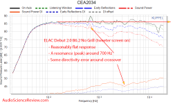
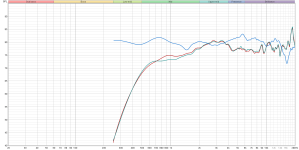
Based on these very quick measurements I would say my measuremt setup is ok. Waveguide is ok. That would only leave the CD's...
OK, I also think this proves that your setup is correct. Then it's quite an unusual driver - very efficient at HF with very broad bandwidth (but also with very little HF damping). Or is there any other explanation?
The HF108 doesn't usually present strangely in other's measurements that I have seen. The Faital factory measurements are made on their LTH horn which is a bit of a beamer. A flat on axis is expected with that kind of horn but not the one you made. Maybe run an impedance sweep of the CD off the horn to see how that compares to factory.
Edit: Do they both measure the same?
Edit: Do they both measure the same?
Last edited:
Ah, is that HF108? I thought it was something else.
Then this is what I measured with HF108 on a similar (a little smaller) horn:

Then this is what I measured with HF108 on a similar (a little smaller) horn:
If I read the polar correctly, the rising high end only appears at the reference angle. And drops fairly steep off axis. That could well be a contribution of this particular horn. A measurement of the bare driver (however useless) could maybe prove that it has a rising top end. But I wouldn't worry too much, the measurement setup does it's work properly.
Tom's mike might need some level correction, it shows about +2dB at 12k compared to Erin's measurement. That is of importance to youngsters.
In the image above up until about 3K things look as expected and there is the beginning of a decline before the response flattens out again. Maybe the mic is not calibrated or the calibration is a little off, scaling in Vituix can make things seem exaggerated. Most cheaper omnidirectional mics start to vary above 2K and need calibration to be accurate.
- Home
- Loudspeakers
- Multi-Way
- Efficient 2-way

