You are being very literal, damping from a purely electrical point of view is not exactly the same as how damping material behaves inside a box. That is a much more complicated problem. Normally lumped elements work well but as you found sometimes something extra finds it's way in that needs a different term to explain it.I don't see how increasing damping would automatically lead to asymmetry.
I was describing the process of adding damping material into the box, there can be a defined point where there is too much. I determine the point of too far to be when asymmetry is introduced. Like in your case just one sheet removed from a specific place worked to get back under that point.
If there wasn't so much damping on one side of the brace to the other, it is possible that insulation on top of the brace wouldn't have had quite the same effect as separating the cabinet into two separate but different spaces. Where the material is placed matters for some effects and not others which only complicates trying to analyse it, or giving people advice.
I chamfered the edge of the enclosure today.
I also did some additional impedance measurements. I stuffed a pillow in the enclosure. No real thoughts behind it, but impedance measurements are very easy to do in the living room.

Blue: reference
Purple: Pillow stuffed behind driver (see image below)
Green: Pillow stuffed on brace

Pillow stuffed behind does lower impedance peak, but does not really alter the asymmetry.
Pillow stuffed on brace lwoers the impedance peak similarly, but does alter the asymmetry.
Not sure if there is anything to learn, but put it here for completeness.
I also did some additional impedance measurements. I stuffed a pillow in the enclosure. No real thoughts behind it, but impedance measurements are very easy to do in the living room.
Blue: reference
Purple: Pillow stuffed behind driver (see image below)
Green: Pillow stuffed on brace
Pillow stuffed behind does lower impedance peak, but does not really alter the asymmetry.
Pillow stuffed on brace lwoers the impedance peak similarly, but does alter the asymmetry.
Not sure if there is anything to learn, but put it here for completeness.
I promise I'll improve my measurement setup
( @mabat )
The first step has been made:

Better waveguide mount (invisible), more open waveguide stand, microphone standard. 0-90 degrees measurements are quite clean to 4 (to 6) ms. After 90 degrees the speaker mounting is increasingly cluttering the measurement. Cleaning that up will need some special waveguide stand; I'm not sure that is worth it. I'm contemplating automating the setup, but the measurements are not always correct. Need to solve that before I can trust it and automate it. No idea what causes it btw. I also asked my ex-father-in-law and can use his barn for even more reflection free time, but I think the speaker stand is more important.
Here are some VituixCAD plots. Window is 4ms, but with a frequency dependent window of 17 cycles. Cleans the FR's HF a tad.

.png")
 2.png")
 b.png")
 2b.png")
ps. This is the second prototype.
Last edited:
A pro loudspeaker 36 mm diameter stand/tripod works really great as a stand for measurements. Just cut a little platform from some leftover wood and print a 36 mm ID tube with a flange to mount it to. You can use the tube as the point of rotation, the waveguide/CD is not too heavy for that and the friction on the tube will hold it in place.
Point is: measure!
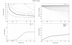
I'm not familiar with Burst Decay Plots, but I tried to take one:

The microphone was close to the woofer (1-2 cm) as I saw that below your image. I also used settings like yours, or at least I tried. I think the angled ridges are reflections and not resonances: equal time needs more periods for higher frequencies.
Looks clean, right?
Look at the spectrogram in Burst Decay mode (not waterfall), that will more closely resemble the ARTA presentation which is easier to interpret.I'm not familiar with Burst Decay Plots, but I tried to take one:
This is a really interesting thread! Just wanted to ask, as a quick review hasn’t made it clear. Which tweeter/CD are you using in this design?
Also your horn looks so great. I might try and build a set of speakers modelled after this at some point (or if you ever release your plans later)!
Also your horn looks so great. I might try and build a set of speakers modelled after this at some point (or if you ever release your plans later)!
Faital pro HF108Which tweeter/CD are you using in this design?
Clean and you are right, those angled ridges are reflections. I’m inclined to think that anything below 25-30dB under reference level can be neglected (need some proof for that tho) so you’re set.I'm not familiar with Burst Decay Plots, but I tried to take one:
View attachment 1151666
The microphone was close to the woofer (1-2 cm) as I saw that below your image. I also used settings like yours, or at least I tried. I think the angled ridges are reflections and not resonances: equal time needs more periods for higher frequencies.
Looks clean, right?
This is the issue with quasi-anechoic data: in the range between the high resolution near-field measurements and where the gated measurement has enough resolution, say 400 Hz to 1.5 kHz, resolution can only be recovered through a bigger gate, which means a big measuring effort. Somewhere in the ath thread you can see the efforts by @Zvu and @Jokerbre, when they put the speakers 2.4 meters (?) high in a sports hall.
Without being able to extend the gate time you can perform a series of near field measurements around the cabinet to see if any resonances are visible that way. Given that the impedance shows very little other than inherent driver resonances I don't think there will be much to see.I'm still a bit puzzled...
Because I'm using a gate to clean up the reflections, I'm also throwing away low frequency resonances. Right? So, how am I ever going to see lowish frequency resonances?
Near field measurements typically enable gates of 40ms and more (at least in my basement). The noise floor (incl reflections) drops rapidly when moving the mike real close to the cone.
Otherwise, ground plane and outdoor measurements are the only options for the last tweaks of any system I think.
Otherwise, ground plane and outdoor measurements are the only options for the last tweaks of any system I think.
Measurement day!
Today I made quite a big step in my measurement setup. I ordered a speaker stand as @pelanj suggested and went to my ex-father-in-law's barn. I planned on printing an adapter to mount the waveguide to the speaker stand, but that ended in a large bowl of PLA spaghetti.
The setup(s):
setup 1:

Height ~1.90m (ground reflection 8.5ms)
setup 2:

Height ~2.60m (ground reflection 12.5ms)
The stands looked quite large in my living room, but they looked very small in the barn. Lot's of free space. The barn is very long and in a certain frequency range I could clearly hear an echo sweep.

The ground reflection is clearly visible at 8.5ms. They are some other reflections just after 5 and 7 ms. Too bad, they result in wiggles in the FR. And you might have notices I have wiggle-fobia.

The ground reflections has been shifted to 12.5ms, nice. The 7ms reflections seems to be gone, but the ~5m reflection is still present. I've tried to get rid of it by covering speaker and microphone stand with foam or clothing, but I was not able to change it.
Can I filter out the 5ms reflection using a special window? A '5ms notch' filter? Before I dive into that and reinvent the wheel again: Has this been done and is it already available in the software?
Here is an overview of all measurements with setup 1 with a 4.5ms window:

Unfortunately some measurements show some ringing:

Does anyone know what causes that?
I imported the measurements into VituixCAD:

I think the DI is very smooth. It is, however, a bit lower than expected. That would force me to crossover a bit lower, right?
.png")
And here is the polar map:
.png")
Today I made quite a big step in my measurement setup. I ordered a speaker stand as @pelanj suggested and went to my ex-father-in-law's barn. I planned on printing an adapter to mount the waveguide to the speaker stand, but that ended in a large bowl of PLA spaghetti.
The setup(s):
setup 1:
Height ~1.90m (ground reflection 8.5ms)
setup 2:
Height ~2.60m (ground reflection 12.5ms)
The stands looked quite large in my living room, but they looked very small in the barn. Lot's of free space. The barn is very long and in a certain frequency range I could clearly hear an echo sweep.
The ground reflection is clearly visible at 8.5ms. They are some other reflections just after 5 and 7 ms. Too bad, they result in wiggles in the FR. And you might have notices I have wiggle-fobia.
The ground reflections has been shifted to 12.5ms, nice. The 7ms reflections seems to be gone, but the ~5m reflection is still present. I've tried to get rid of it by covering speaker and microphone stand with foam or clothing, but I was not able to change it.
Can I filter out the 5ms reflection using a special window? A '5ms notch' filter? Before I dive into that and reinvent the wheel again: Has this been done and is it already available in the software?
Here is an overview of all measurements with setup 1 with a 4.5ms window:
Unfortunately some measurements show some ringing:
Does anyone know what causes that?
I imported the measurements into VituixCAD:
I think the DI is very smooth. It is, however, a bit lower than expected. That would force me to crossover a bit lower, right?
And here is the polar map:
Attachments
Last edited:
The position of the mic stand can be a problem see this from B&K

That is why I went to the trouble of designing a tube mount, so the mic can sit in the end of a 2m tube.
If only you could remove reflections with simple software hacks there would be no need for difficult physical setups")
Ringing depends on the window used as well, you look to have a rectangular one at the right which will have the most ringing. Pre ringing of that type is often from linear phase reconstruction filters in DAC's, the period will probably correspond to around Nyquist at the sample rate.
Pattern looks to be 45 to 50 degrees at 800 Hz which should be right for a 15" woofer. The DI is smooth and doesn't give out abruptly so the crossover can work over a wider range than it would if the DI collapsed quickly.
That is why I went to the trouble of designing a tube mount, so the mic can sit in the end of a 2m tube.
If only you could remove reflections with simple software hacks there would be no need for difficult physical setups
Ringing depends on the window used as well, you look to have a rectangular one at the right which will have the most ringing. Pre ringing of that type is often from linear phase reconstruction filters in DAC's, the period will probably correspond to around Nyquist at the sample rate.
Pattern looks to be 45 to 50 degrees at 800 Hz which should be right for a 15" woofer. The DI is smooth and doesn't give out abruptly so the crossover can work over a wider range than it would if the DI collapsed quickly.
The microphone stand probably produces minor reflections. Mounting the mike on the end of a long tube might help. I used a metal broom stick and mounted an XLR connector at the end.
The position of the mic stand can be a problem see this from B&K
I remember you guys said that before. I even bought pvc tubing some time ago, but haven't taken the time to make something useful out of it. I try to listen to all advice, even though it might take some time to implement it.
In the mean time I tried to filter out clear reflections (only) and the result does not look like complete rubbish.If only you could remove reflections with simple software hacks there would be no need for difficult physical setups
The 'ringing' is present in (some) raw measurements and can have different frequencies. Repeating the measurement is often enough to get one without ringing, which suggests to me that it might be caused by other sound picked up during the test, as that it one of the few things things that aren't repeatable, right?Ringing depends on the window used as well, you look to have a rectangular one at the right which will have the most ringing. Pre ringing of that type is often from linear phase reconstruction filters in DAC's, the period will probably correspond to around Nyquist at the sample rate
I have preliminary measurements of my woofer that indicate that my 12" is already large. I guess I will need better measurements first and than check again.Pattern looks to be 45 to 50 degrees at 800 Hz which should be right for a 15" woofer. The DI is smooth and doesn't give out abruptly so the crossover can work over a wider range than it would if the DI collapsed quickly.
Constructing some crossover that has a smooth on axis result and a smooth DI feels a bit magic. Is there a recipe of steps that will achieve that in a more straightforward manner?
What exactly did you do?In the mean time I tried to filter out clear reflections (only) and the result does not look like complete rubbish.
Sine sweeps are very good at rejecting noise but trying to troubleshoot someone else's measurement setup is hard through a forum.The 'ringing' is present in (some) raw measurements and can have different frequencies. Repeating the measurement is often enough to get one without ringing, which suggests to me that it might be caused by other sound picked up during the test, as that it one of the few things things that aren't repeatable, right?
There should be no need of magic, your raw measurements of the waveguide look strange to me though, the DI and normalized directivity is as expected but everything else looks quite odd. Waveguides of that type should peak towards the lower end and fall to high frequencies without correction.Constructing some crossover that has a smooth on axis result and a smooth DI feels a bit magic. Is there a recipe of steps that will achieve that in a more straightforward manner?
- Home
- Loudspeakers
- Multi-Way
- Efficient 2-way