Hello,
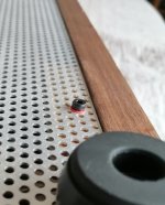
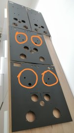
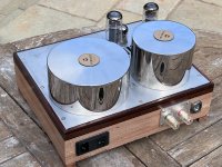
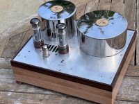
I'm laying out the output transformers and the toroidal power transformer on the top side for my BH EL34 amplifier.
what is the minimum recommended separation between the EL34 and the nearest transformer, mainly a heat issue that I'm trying to stay clear of while ensuring that the layout isn't too spaced out
Earl Josh
Calculate the total heat that is coming off of the EL34.
I do not know the plate to cathode volts and plate current; the screen to cathode volts and screen current of the versions of the Baby Huey.
But . . .
6.3V x 1.5A = 9.45 Watts (filament)
and suppose we have:
Plate to cathode 350V at 50mA; 350 x 0.05 = 17.5 Watts
Screen to cathode 300V at 5mA; 300 x 0.05 = 1.5 Watts
9.45 + 17.5 + 1.5 = 28.45 Watts total
If instead, you max out the tube, you have 25 Watts in the plate, 8 Watts in the screen, and 9.45 Watts in the filament,
you have 42.45 Watts of heat coming out of the tube. Ouch! Do not do that.
Space the EL34 to other parts accordingly.

Orientation of the tube can matter, since more heat is radiated from the flat sides of the anode. I would have thought 5cm/2" is ok. A lot is said here about spacing, but when I look at my Quad IIs it is just a couple cm between everything. I think having the tubes exposed is probably the key thing.Hello,
I'm laying out the output transformers and the toroidal power transformer on the top side for my BH EL34 amplifier.
what is the minimum recommended separation between the EL34 and the nearest transformer, mainly a heat issue that I'm trying to stay clear of while ensuring that the layout isn't too spaced out
Earl Josh
Hi,
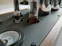
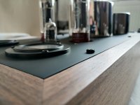
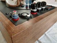
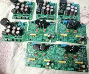
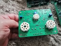
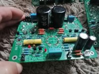
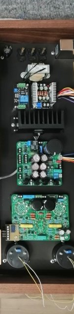
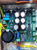
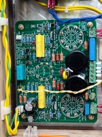
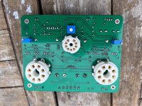
EL34 Baby Huey PSU assembly completed. I have some questions.
Transformer technical information:
Seconder1................:260vac 400ma
Seconder2................:13vac 4amp.
Seconder3................:7vac 4amp.
Seconder4................:48vac 200ma
DC output:
+HV-GND........:350v dc
DC/DC/.............:17.16 dc
DRIVE/GND....:16,9 dc
Bias/GND........:-129v dc
1-Will EL34 Baby Huey work with these psu output values?
2-bias voltage max-100vdc in the diagram. PSU bias voltage -129vdc. Will I have a problem?
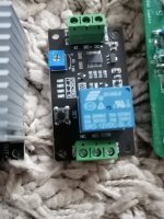
3-The voltage relay on the +HV terminal takes a long time to open. About 30-40 seconds. Is this normal.
EL34 Baby Huey PSU assembly completed. I have some questions.
Transformer technical information:
Seconder1................:260vac 400ma
Seconder2................:13vac 4amp.
Seconder3................:7vac 4amp.
Seconder4................:48vac 200ma
DC output:
+HV-GND........:350v dc
DC/DC/.............:17.16 dc
DRIVE/GND....:16,9 dc
Bias/GND........:-129v dc
1-Will EL34 Baby Huey work with these psu output values?
2-bias voltage max-100vdc in the diagram. PSU bias voltage -129vdc. Will I have a problem?
3-The voltage relay on the +HV terminal takes a long time to open. About 30-40 seconds. Is this normal.
Attachments
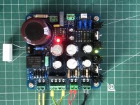
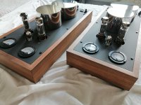
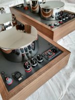
Finally....

Attachments
-
 IMG_20230619_131626.jpg363.1 KB · Views: 212
 -
 IMG_20230619_132020_edit_232476330047338.jpg408.3 KB · Views: 203
 -
 IMG_20230619_131851.jpg257 KB · Views: 198
 -
 IMG_20230619_130932.jpg282.7 KB · Views: 187
 -
 IMG_20230619_130844.jpg252.8 KB · Views: 194
 -
 IMG_20230619_131119_edit_232579178949926.jpg386.2 KB · Views: 208
 -
 IMG_20230619_111828.jpg236.2 KB · Views: 222
 -
 IMG_20230617_163543_edit_190381751030324.jpg478.4 KB · Views: 215
 -
 IMG_20230619_121449.jpg374.2 KB · Views: 190
 -
 IMG_20230619_132528_edit_231788003481297.jpg236.2 KB · Views: 185
Hmmm.... not really... sort of..but I'll try on next ones....
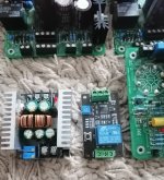
I used a much bigger heathsink for rectifier.....
I used a much bigger heathsink for rectifier.....
Attachments
-
 IMG_20220713_191431_edit_652423939431175.jpg623.7 KB · Views: 170
 -
 IMG_20230508_150717_edit_653041240863372.jpg377.7 KB · Views: 172
 -
 IMG_20230508_150707_edit_653053041140974.jpg355.5 KB · Views: 163
 -
 IMG_20230508_150950.jpg292.3 KB · Views: 169
 -
 IMG_20230508_150937_edit_653249641678965.jpg466.2 KB · Views: 164
 -
 IMG_20230508_151038_edit_653236354933655.jpg353.1 KB · Views: 166
 -
 IMG_20230607_180719.jpg162.4 KB · Views: 171
This is the series: https://m.it.aliexpress.com/item/1005002515096980.html
Sorry for late reply...
This is the link:
https://www.ebay.com/itm/173095200763
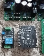
Make sure to buy more because I saw some bad packaging and some of them need more "attention" for recalibration...
Also you need to cut the shunt resistors from inside, do recalibration for this project and a delay timer is a better choice to do.
This is the link:
https://www.ebay.com/itm/173095200763
Make sure to buy more because I saw some bad packaging and some of them need more "attention" for recalibration...
Also you need to cut the shunt resistors from inside, do recalibration for this project and a delay timer is a better choice to do.
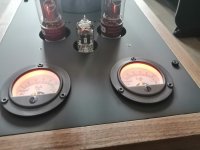
I'm guessing (because this is what I'm doing). Buy 100 mA meters like those, because they say "100 mA" on the scale. But open them up, remove the internal shunt, and convert them to voltmeters by adding an appropriate series resistor calibrated so that 1 volt gives full scale deflection, ie, up to the "100 mA" mark. Then use these meters across 10R resistors in the bias circuits so they correctly display in "mA", with 100mA giving 1 volt at full scale. V = I x R ........ 1.0v = 0.100A x 10R.
While you have the meters opened up, add a couple of yellow LEDs (which use maybe 10 - 15 mA each at a couple of volts) to be powered off some low voltage source in the amp (heater tap into appropriate series resistor, diode or two, capacitor?).
Maybe the delay timer is to auto-disconnect the meters and LEDs after 15 minutes?
Simon
Simon explanation is perfect....
I use only a single led for ilumination (3mm amber 1,8V) and powered via resistor from 12V source.
Delay for mA is used because when amplifier is powered up, there is (for a second), a bigger current across 10 ohms resistors (more than 100mA) and I wanted to protect the meters from that.
Do to transport issues, the screws from indicator plate, (inside meters), can become loose and need aditional atention....
Trying to test the first of my monoblocks, but the bias current is far too high - something must be wrong 😕. TP1/2-GND shoot up to c. 3VDC as soon as the timer clicks and the EL34s start to redplate, so I kill the power.
The trimmer pots don’t seem to make a difference - I did wonder if I’d got them the wrong way round, as they’re on the back of the pcb the adjustment screw is on the opposite side to that printed on the front.
I’m a tube noob so any advice where to look or a solution is much appreciated.
Other measurements:
+HV-GND = 409 VDC (275 VAC secondary)
DRIVE-GND = 17.2 VDC
-VBias-GND = -94.6 VDC
C1/C2 = 16mV min (with trimmer fully anti-clockwise)
Timer takes a long time - about 90 seconds
 Dom
Dom
The trimmer pots don’t seem to make a difference - I did wonder if I’d got them the wrong way round, as they’re on the back of the pcb the adjustment screw is on the opposite side to that printed on the front.
I’m a tube noob so any advice where to look or a solution is much appreciated.
Other measurements:
+HV-GND = 409 VDC (275 VAC secondary)
DRIVE-GND = 17.2 VDC
-VBias-GND = -94.6 VDC
C1/C2 = 16mV min (with trimmer fully anti-clockwise)
Timer takes a long time - about 90 seconds
Attachments
-
 36E7227A-A848-441F-ADFA-2B6E462F25E5.jpeg805.6 KB · Views: 99
 -
 55B20417-9205-4B7C-BE64-42ECD26598B4.jpeg818.1 KB · Views: 111
 -
 A51B59AC-B8AD-4639-B3AC-FF1AFE79CA9E.jpeg946 KB · Views: 123
 -
 7FD99F92-0884-423F-8D3B-427C800445AB.jpeg984.6 KB · Views: 126
 -
 430861A1-6E3D-4F9E-AB91-93C0D3445F3E.jpeg807.2 KB · Views: 118
Hi Domg,
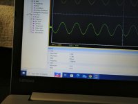
Your B+ is well within limits for your outputs. The only reasons why the plates would overheat is either your grid bias isn't as negative as you think it is, or the tubes are oscillating. I would pull the outputs and power up the amp partially (please have a variac). Measure the voltages at the grid pins on the output sockets and report back.
To see if it is oscillating, you need an oscilloscope or spectrum analyzer. An oscilloscope would be the normal instrument to use. Much cheaper too!
- Home
- Amplifiers
- Tubes / Valves
- EL34 Baby Huey Amplifier