This post contains a link to the ESS downloads page. There are some schematics in the "Maximizing DAC performance..." document that will effectively run the DACs in current mode. You may notice there are inverting opamp circuits with no input resistor. That effectively creates a virtual ground (actually a virtual offset node of approximately zero input impedance) that sinks (or sources) current from (or to) the DAC outputs. What is missing from that document is mention of how to get the so-called reference voltage that you would need. It does, however, show how to condition AVCC power to produce the 3.3 volts to feed the reference divider.
The rest of what you would need is shown in the schematic for the evaluation board which is also available on the downloads page. The schematic shows that a voltage divider and capacitor filter at the output of the divider are used to create a reference voltage for each of the two output channels, left and right. The voltage divider should be connected to the 3.3volt highly conditioned AVCC power for each channel.
You may also find some information you can use in the following posts:
http://www.diyaudio.com/forums/digital-line-level/314935-es9038q2m-board-43.html#post5384519
http://www.diyaudio.com/forums/digital-line-level/314935-es9038q2m-board-44.html#post5385456
Could someone show me the easiest way to put the Dac in current mode?
I followed the advice of Madds1 post # 355 but the indicated resistance seems irrelevant, I tried all the values between 0 and 3.2M.
I'm a beginner, could you show some images too?
Any suggestions?
With no slight towards Madds1's contribution, he's generally playing around and giving his impressions rather than going through a deliberate, targeted approach like Mark (+Jens, Victor, Vacuphile, et. al). Which is really going to make it difficult for others to find useful. JensH gave a schematic earlier in this thread of an opamp I/V (current to voltage, i.e. transimpedance amplifier) that will look very similar to the one that Mark linked. Pay attention to those, as that will give you the best chance of understanding what you're doing. As I wrote earlier, the "voltage mode" versus "current mode" is simply a matter of the load impedance placed on the DAC, which very definitely includes the input impedance of the circuit following the DAC. The stock configuration places a noninverting buffer as the load, which will present a very high impedance to the DAC, thus operating it in "voltage mode", whereas the transimpedance amplifier circuits mentioned above will provide a low load impedance to the DAC.
Good luck!
This post contains a link to the ESS downloads page.
Sorry, looks like the link is missing. Here the post that contains the link, and possibly some other useful information: http://www.diyaudio.com/forums/digital-line-level/314935-es9038q2m-board-42.html#post5383552
Last edited:
With no slight towards Madds1's contribution, he's generally playing around and giving his impressions rather than going through a deliberate, targeted approach like Mark (+Jens, Victor, Vacuphile, et. al). Which is really going to make it difficult for others to find useful. JensH gave a schematic earlier in this thread of an opamp I/V (current to voltage, i.e. transimpedance amplifier) that will look very similar to the one that Mark linked. Pay attention to those, as that will give you the best chance of understanding what you're doing. As I wrote earlier, the "voltage mode" versus "current mode" is simply a matter of the load impedance placed on the DAC, which very definitely includes the input impedance of the circuit following the DAC. The stock configuration places a noninverting buffer as the load, which will present a very high impedance to the DAC, thus operating it in "voltage mode", whereas the transimpedance amplifier circuits mentioned above will provide a low load impedance to the DAC.
Good luck!
That is correct. I did not take a targeted approach for this board. I played with it in voltage mode as it was and then shifted to current mode without reworking the entire circuit using a single opamp by putting one leg on the inverting pin into virtual ground and putting a cap to the ground for the other pin which will makes a low pass so that all AC sees a constant voltage. It is a quick and simple way to get to a non-differential current mode using one opamp
My goal was to see if this chip had potential and it does. But like others have discovered, the board layout and voltage supplies need too much reworking to get a good clean output
Hope this helps
Cheers
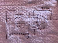
Apologies for the napkin drawing. Sitting at a bar in Mexico 😊
Shown in the pic is the easiest way to get a Sabre sac to current mode. Simply set the feedback resistor to be equal to the internal resistance of the DAC. The other pin can be used as a voltage reference and grounded using a LPF
Shown in the pic is the easiest way to get a Sabre sac to current mode. Simply set the feedback resistor to be equal to the internal resistance of the DAC. The other pin can be used as a voltage reference and grounded using a LPF
Attachments
Don't know why it would matter if the feedback resistor were the same as the DAC internal resistance or not. It seems like it should only have the effect of scaling the output voltage to no more than 3.3v peak-to-peak.
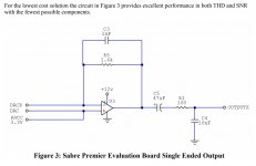
For a very simple circuit, ESS have their own recommendation as shown below.
For a very simple circuit, ESS have their own recommendation as shown below.
Attachments
Last edited:
Yes. Very correct. Feedback resistor value doesn’t matter in either circuit. In one of my earlier post I mentioned was getting a DC offset and that the feedback resistor was the culprit. It is not. I was mistaken. Not sure why I said that 🧐
Could it be the 3.3K prior to the input pins is causing the offset? Will check I get back home from my vacation
Could it be the 3.3K prior to the input pins is causing the offset? Will check I get back home from my vacation
Madds1, it can't be done like this. As Mark already remarked, the value of the feedback resistor doesn't matter, the inverting node is always virtual ground (plus offset in this case). The non-inverting connection doesn't make sense like that. It certainly will not put the negative output of the DAC in current mode. The only way to do that is to give that output its own dedicated opamp.
The Sabre recommendation is puzzling. To bias the non-inverting input of the opamp to AVCC will turn it into a phase splitter if it is rail-to-rail, at best. Biasing this input to around 1/2 AVCC would make more sense. In that case, only one output of the DAC is being used, but that is not a real problem distortion wise, just reduces PSSR of the reference input on the DAC to zero.
In short, for current mode operation you need at least two opamps. Victor showed an elegant schematic to get single ended output from this without using a third opamp.
Don't know why it would matter if the feedback resistor were the same as the DAC internal resistance or not. It seems like it should only have the effect of scaling the output voltage to no more than 3.3v peak-to-peak.
For a very simple circuit, ESS have their own recommendation as shown below.
thank you,
I bought everything necessary
Madds1, it can't be done like this. As Mark already remarked, the value of the feedback resistor doesn't matter, the inverting node is always virtual ground (plus offset in this case). The non-inverting connection doesn't make sense like that. It certainly will not put the negative output of the DAC in current mode. The only way to do that is to give that output its own dedicated opamp.
The Sabre recommendation is puzzling. To bias the non-inverting input of the opamp to AVCC will turn it into a phase splitter if it is rail-to-rail, at best. Biasing this input to around 1/2 AVCC would make more sense. In that case, only one output of the DAC is being used, but that is not a real problem distortion wise, just reduces PSSR of the reference input on the DAC to zero.
In short, for current mode operation you need at least two opamps. Victor showed an elegant schematic to get single ended output from this without using a third opamp.
so I only made unnecessary changes.
thanks for the information
One other thing I might mention, the digital volume control built-in to the DAC, and accessible on the 1.06 Chinese DAC PCB by connection of a 10k pot to a 3-pin header, tends to mostly operate only over about half the pot rotational range. Also, making the pot wiper more + turns down the volume. Therefore, an easy fix might be to use a 5k pot and connect a 5k fixed resistor in series with the end of the pot that connects to the + header terminal. That should make the pot effective for volume control over most of its rotational range.
The Sabre recommendation is puzzling. To bias the non-inverting input of the opamp to AVCC will turn it into a phase splitter if it is rail-to-rail, at best. Biasing this input to around 1/2 AVCC would make more sense. In that case, only one output of the DAC is being used, but that is not a real problem distortion wise, just reduces PSSR of the reference input on the DAC to zero.
I thought that was a typo and meant to be 1/2 AVCC as well. If it is as recommended then, yes, it's pretty counterintuitive.
I thought that was a typo and meant to be 1/2 AVCC as well. If it is as recommended then, yes, it's pretty counterintuitive.
I agree it looks counterintuitive, but that is probably only because we don't know exactly what is going on inside the DAC, only ESS knows that.
For anyone wanting to implement such a circuit please remember proper power supply bypassing is commonly omitted from schematics, but essential for good performance and stability.
Also, probably wise to choose an appropriate opamp. ESS is quite clear about which opamps they think are most suited for maintaining signal quality the DAC is capable of providing. LME49710 is one good choice if using singles, and LME49720 if using a dual.
How is everyone finding their ES9038 boards?
I've messed with a lot of DACs over the years and enjoying building new projects, I was bored and thought I'd order a ES9018 board from China to mod, then started looking at ES9028 and now ES9038!
After building and owning far to many DACs to mention, also got a few old CD Players in the workshop to pull out the TDA1541's to build a DAC (for curiosity)
I bought a Chord Qute EX (FPGA) DAC and haven't messed for a while, but being an electronics engineer I must fiddle so will probably order a ES9028/38 board from China to play with and originally was just for fun and nothing to use seriously, but now I'm wondering could I replace the Chord Qute EX with it? Will it be as good or better.
I have a few NOS Noritake VFD's here that I was going to put in a box with a cheap DAC board and a Pi for something to listen to in Kitchen/Bedroom with an ES based board inside.
Anyway thought I'd say Hi and interested to know what everyone thinks of these ES9038 boards.
The Chord Quote is a very good DAC. On upgrade to 2qute is a straight forward step, and highly recommended! It is right to know, that these Chinese 9038Q2M DAC panel (and all the ES based 90... brothers) was not intended to use by the audiophile community. You could just check the Twisted Pear topics/homepage for serious DIY implementation of ES dacs. But these small ES9038Q2M board is cheap enough to play with. Modding the board is relatively easy and upgrading is just for fun is a nice experiment.
Despite of the fact that to do some mods you sould have some knowledge, I will try to help.
Indeed, AMS1117 have 3 pins - see datasheet. Namely, tab is the same connection as pin 2 (VOut). And at our board VOut trace is connected to tab (not to pin 2). Pinout of AMS1117 is:
1. Ground
2 and Tab - VOut
3. VIn
As I remember, in your small PCB with LT3045 pinout is the same as L7805 (for example, see datasheet too), i.e.
1. VIn
2. Ground
3. VOut
So, you need:
- desolder AMS1117
- place your PCB with LT3045 on original board somewhere near the L7805 (or 7808, it depends on version of original DAC)
- solder pin 1 of that PCB to pin 3 of L7805 in case of ver 1.06 (or L7808 in ver. 1.04)
- solder pin 2 of that PCB somewhere to ground (I think the simplest way is to do it via the existing hole to bottom layer)
- solder pin 3 of that PCB to the trace where tab of AMS1117 has been soldered
That's all. See also my picture in the post #336 for your reference (in that case pin 1 of my patch PCB is VOut, pin 8 is VIn, pins 3,6,7 is ground).
Hi,
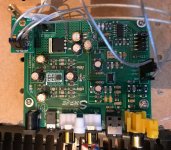
I just replaced ams1117 by lt3045.
Thank you to all who helped about the procedure and the desoldering advices.
I can't make THD and SNR measurements, But to my ears, noise is no more perceptible, the soundstage is way bigger and the music sounds more vivid.
Attachments
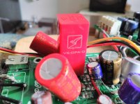
Burson V5 among the best
As I reported earlier here, I have separated many of the power supplies of the 1.04 board using Superregs, Salas BiBs and others. So it was high time to serious tests of OPAs! But I fed up soon (boring opa rolling") ), so finally I bought this guy. It is huge sized, and the sound of Burson V5 opa is just huge too. The factory recommendation is to install 2x 220 uF Elna Silmic II at the power legs. One of my friend had a great success using Elna-s. I put two old 100 uF/16V BG N caps instead of the onboard Elna RA3-s. Bgs are huge too, and because of the lack of enough space, it is not an easy job to solder them in place, but i managed to do.
), so finally I bought this guy. It is huge sized, and the sound of Burson V5 opa is just huge too. The factory recommendation is to install 2x 220 uF Elna Silmic II at the power legs. One of my friend had a great success using Elna-s. I put two old 100 uF/16V BG N caps instead of the onboard Elna RA3-s. Bgs are huge too, and because of the lack of enough space, it is not an easy job to solder them in place, but i managed to do.
As I reported earlier here, I have separated many of the power supplies of the 1.04 board using Superregs, Salas BiBs and others. So it was high time to serious tests of OPAs! But I fed up soon (boring opa rolling
), so finally I bought this guy. It is huge sized, and the sound of Burson V5 opa is just huge too. The factory recommendation is to install 2x 220 uF Elna Silmic II at the power legs. One of my friend had a great success using Elna-s. I put two old 100 uF/16V BG N caps instead of the onboard Elna RA3-s. Bgs are huge too, and because of the lack of enough space, it is not an easy job to solder them in place, but i managed to do.Attachments
Last edited:
The Chord Quote is a very good DAC. On upgrade to 2qute is a straight forward step, and highly recommended! It is right to know, that these Chinese 9038Q2M DAC panel (and all the ES based 90... brothers) was not intended to use by the audiophile community. You could just check the Twisted Pear topics/homepage for serious DIY implementation of ES dacs. But these small ES9038Q2M board is cheap enough to play with. Modding the board is relatively easy and upgrading is just for fun is a nice experiment.
Thank you for the reply.
I won't be upgrading to the 2Qute, there is actually no difference in the real world, just lots of heavy marketing and snake oil on review sites. Yes its a slightly bigger FPGA but even the one on the Qute EX is too powerful for just a DAC, but people love specifications and technically on paper it is more powerful. But that's like having a 600hp engine in a fiesta, you can't use that power
I think I'll order the ES9038 board and have a play around with it and make some improvements, will probably re-cap the board as a lot of these have offbrand caps or "Fake" and I don't believe in "Audio" grade electrolytic capacitors, I just want to make sure the ESR/value and longevity etc is correct.
At the moment I use a custom built PC made out of solid cast metal running a J1900 and fanless, using Daphile OS as I've had squeezebox systems since they came out and I suppose I'm used to that system, with the DAC running Async USB 2.0.
But will be interesting to see what a Pi or another small board can offer me with a I2S dac.
Looking forward to having a play, just have to decide which ES9038 board to go for
This looks an interesting kit, as you can test the components first before you fit them, also fit components of your own choice or do mods.
Not sure if it's available cheaper from Aliexpress etc, just popped up on my eBay search:
ES9038 ES9038PRO DAC decoder board + TCXO + remote control DIY KIT | eBay
Not sure if it's available cheaper from Aliexpress etc, just popped up on my eBay search:
ES9038 ES9038PRO DAC decoder board + TCXO + remote control DIY KIT | eBay
- Home
- Source & Line
- Digital Line Level
- ES9038Q2M Board