Hate to have to destroy the clock to replace.
Some of the clocks commonly seen cost less than a dollar each. Few are worth more than 2 or 3 dollars. What hurts is having to pay more for shipping than for parts.
Okay. How far away are the batteries and what kind of wire? Are we trying to compensate for resistance, inductance? ESS seemed to think having the power source very close to the AVCC pins was important. But they only used electrolytic caps at the output of the AVCC opamps.
Sorry I was looking at VDD path not AVCC.
I've snipped off the OSCONs and put all the PS wiring as close as the board allows. Doing that brought out further refinement. Aside from the clock and messing with output stage I don't think I can take this much further right now. But wow, music sounds so good. Power supply, man, so important.
Attachments
Well I powered up my daughter board holding the power supply and AVCC regs and IV.
It powered up fine intially without the op amps and I measured voltages. Perfect so far.
Then I popped in a couple dual TL072 op amps and then measured voltages. This was with the board not connected to the dac. I got voltages at the output. Hmm I even got AVCC output when there was no feed to the input filter for AVCC.
Then I changed the op amps and used some NE5532s. The voltages changed. Double and triple checked the circuits. Then I put in an LME49720 for the AVCC reg and the voltage changed again. Then I checked the input voltage before the filter and it was around 1v.
Ok, I am not an expert at op amp connections but it appears that the op amp was charging the filter cap on the input of the AVCC reg.
So I connected a battery pack that was generating 4.6 V to the input of the AVCC filter and the reg put out exactly the same voltage. So the regulator does work. At this point my only test for instability is temp. All the op amps were running cool and so was the voltage reg. I am scared that I will have to catch my woofers across the room.
I imagine that the open inputs is causing some offsets. I hope so.
Next few days the connection to the DAC.
You could check by putting resistors in series with your opamp outputs and running that into some headphones or earphones. It will load down the opamps and increase distortion if the resistors are too small, or make the headphones quiet and maybe flabby if too large, but at least you could get some idea of what is coming out before hooking it up to a full-sized stereo.
Also, some opamps have input protection diodes that may conduct if you allow the inputs to get too far apart or float. No inputs should be fully floating, some kind of resistor to ground or an intermediate reference voltage would probably be okay for initial testing. Input bias currents need somewhere to flow to or from.
Also, some opamps have input protection diodes that may conduct if you allow the inputs to get too far apart or float. No inputs should be fully floating, some kind of resistor to ground or an intermediate reference voltage would probably be okay for initial testing. Input bias currents need somewhere to flow to or from.
Last edited:
I will measure the offset voltages at the output before connecting to a preamp and even then I will put it on passive preamp on my office system first. I am not skilled at understanding the details of op amps and various configurations. Thanks for the advice. It is proceeding nicely so far.
One may find that TL072 can actually be quite good if driving higher z loads, say, at least a couple of k-ohms. Distortion increases a lot with more output loading. I/V conversion is probably going to load them more than optimal for hi-fi use.
Most likely, it will turn out that ESS did their homework and the opamps they recommend are the ones that work best. Just, sayin'.
Most likely, it will turn out that ESS did their homework and the opamps they recommend are the ones that work best. Just, sayin'.
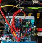
@wushuliu, What kind of DAC is that in the picture? Don't recognize it myself.
It's the Hifimediy UAD38Pro.
It looks like the same Chinese company that makes the ES9038Q2M DAC boards is now also making their own SRC board.
It is cheaper from Ali Express than ebay, or so it appears:
sandy AK4137 DAC SRC Audio 384K 32Bit DSD256 DSD IIS Conversion-in Headphone Amplifier from Consumer Electronics on Aliexpress.com | Alibaba Group
HiFi AK4137 DAC SRC Audio Decoding Board PCM 384K 32Bit DSD256 IIS Conversion 142372810754 | eBay
Besides the fancy user interface and higher cost, the SRC chip on this one might be a little better than the SRC4392 board, although the latter is probably more than good enough.
It also may well be worse.
There is no information WRT jitter rejection slope or corner freq of AK4137 and I was not able to get any
solid information from AKM WRT (digital) PLL's performance. In fact they didn't appear to know what I
was talking about which was curious.
On the other hand 4392 has very good jitter rejection / low CF, as indicated in data sheet.
T.
Last edited:
I don't understand what you mean about using a 3042 to make the reference voltage for the IV stages. It makes no sense to me unless you are using the same 3042 to power AVCC.
Please see the diagrams below. The point marked "offset" is another name for "reference voltage." That is the correct way to make the reference voltage.
I'm not sure driving an opamp directly into a capacitor for AVCC is a particularly
good idea. You are probably better off using a small series resistor at opamp
output and then closing loop after that resistor. Refer to typical ADC IP circuit
for driving large caps required at ADC input.
T
It's the Hifimediy UAD38Pro.
Looks like you might be able to get the big clock off if you have a helper and two soldering irons. You could pry a little under one end with a jewelers screwdriver and heat the two end pins at once, assuming it has four pins of course. Work up one end a little then the other. Once it gets up high enough it might be possible to get under it and cut the pins.
Some people might try putting metal tape and or Mylar tape around everything but the clock then heat the clock can from the top with hot air (heat gun) or a radiant heater while using chip quik de-soldering alloy on the bottom.
The most certain way to get it off and avoid damaging anything else would probably be to cut open the top of the can and start disassembling it from the top. Don't know how many things I cut open with my trusty, old electronics diagonal cutters over the years. Finally moved up to a Dremel tool, which can make it easier, but still doable without, IMHO.
So far as I know those gold-color large-ish clocks go for about $10 on ebay: 1pc 80MHz TCXO 0.1ppm Ultra precision Golden Oscillator for USB DAC audio | eBay
but they are not ultra low-jitter down at 10Hz or 1Hz so probably not really worth $10 for audio. Temperature compensated clocking is not critical for our purposes.
I'm not sure driving an opamp directly into a capacitor for AVCC is a particularly
good idea.
Actually, it is a very good idea in this case. It has been tested and recommended by ESS if you read the application note carefully. Of course, one should use the opamp and cap they recommend. Otherwise it may not work.
For anyone who may be interested, here it is: http://www.esstech.com/files/4514/4095/4306/Application_Note_Component_Selection_and_PCB_Layout.pdf
It also may well be worse.
There is no information WRT jitter rejection slope or corner freq of AK4137 and I was not able to get any
solid information from AKM WRT (digital) PLL's performance. In fact they didn't appear to know what I
was talking about which was curious.
On the other hand 4392 has very good jitter rejection / low CF, as indicated in data sheet.
T.
Interesting. On the other hand though jitter may not be the only consideration. The AK4137 has some features that some might find preferable other than in the area of jitter, for example if feeding it from an Amanero board one can use the AK4137 board to handle any type of input possible over USB including DSD, DoP, 384kHz PCM, etc. OTOH, SRC4392 which is a good chip only works up to 192kHz (217kHz, actually?) and is primarily designed for SPDIF/AES I/O with the I2S/PCM serial ports being somewhat secondary. For example there is no guaranteed way to avoid slip errors in PCM slave mode. The SRC can only be directly configured to serve the needs of the DIT.
You have got me curious about the jitter though. I will try to find a way to test one of the AK4137 boards although it may take awhile.
Last edited:
Actually, it is a very good idea in this case. It has been tested and recommended by ESS if you read the application note carefully. Of course, one should use the opamp and cap they recommend. Otherwise it may not work.
For anyone who may be interested, here it is: http://www.esstech.com/files/4514/4095/4306/Application_Note_Component_Selection_and_PCB_Layout.pdf
Just because ESS recommends it doesn't automatically make it a good idea. LoL
")
I would personally feed a square wave (current) into proposed AVCC supply
and look at how this is dealt with. The circuit with most civilized OP response
would be my choice. Obviously you would do THD and above all listen to
various iterations.
It is a very important one from sonic perspective. Go back and have a listenInteresting.
On the other hand though jitter may not be the only consideration.
to some of the early ASRC chips and you will get where I am coming from.
The AK4137 has some features that some might find preferable other than in the area of jitter, for example if feeding it from an Amanero board one can use the AK4137 board to handle any type of input possible over USB including DSD, DoP, 384kHz PCM, etc. OTOH, SRC4392 which is a good chip only works up to 192kHz (217kHz, actually?) and is primarily designed for SPDIF/AES I/O with the I2S/PCM serial ports being somewhat secondary. For example there is no guaranteed way to avoid slip errors in PCM slave mode. The SRC can only be directly configured to serve the needs of the DIT.
You have got me curious about the jitter though. I will try to find a way to test one of the AK4137 boards although it may take awhile.
This would be difficult to measure without good phase noise measuring
equipment. Ironically AKM will know this through the design itself. I suspect
that a/ their support engineers just don't have time or inclination to talk to
the design ppl or b/ it doesn't do particularly well in this department so
specs not published. Obviously flexibility and multitasking was a key
consideration.
T
Just because ESS recommends it doesn't automatically make it a good idea. LoL
I don't have a problem with trusting what they have done and recommend, at least at this point.
AVCC has zero PSRR that I know of and they want minimal series resistance. I doubt they would have gone to a circuit that looks like it should oscillate unless more standard approaches, such as with a series resistor as you mentioned were tried first and didn't perform up to what was needed.
They say if you do it their way you can get -120dB THD, and measurements at Richard Marsh's showed that's what I got. It sounds good too, not too far from the DAC-3 but obviously not as good. There is still the matter of external interpolation filter DSP but that is beyond what I am up for in this project.
I suspect
that a/ their support engineers just don't have time or inclination to talk to
the design ppl or b/ it doesn't do particularly well in this department so
specs not published.
T
Could be. I will start off by seeing if I can do some listening tests. If somebody else has jitter test equipment good down at 10Hz or even better 1Hz I would be happy to send it off to be measured. Have to wait till I can get something here first though.
So far as I know those gold-color large-ish clocks go for about $10 on ebay: 1pc 80MHz TCXO 0.1ppm Ultra precision Golden Oscillator for USB DAC audio | eBay
but they are not ultra low-jitter down at 10Hz or 1Hz so probably not really worth $10 for audio. Temperature compensated clocking is not critical for our purposes.
Yeah. I think I may take a chance and replace with a Connor Winfield VBLD861-Series. Looks pretty new, specs seem good.
- Home
- Source & Line
- Digital Line Level
- ES9038Q2M Board