


Yes I am aware I need to post measurements. It has been a long day toiling over the amp with no real resolution. I have been comparing voltage points from the other channel thats fine. Will get to it soon enough. Thanks.pics no good, we need more detailed ones, in general
post schematic, edited with your measurements in adequate points ( having reference voltages)
two are most important - voltages across LU and voltage at output node (inside pin of output cap)
if you have comparative voltages between channels, one being good ( I suppose that one showing 0.5% THD is good) while other being problematic, I see no other reason than damaged/problematic LU
practically - that being most problematic part - second active is mosfet in Aleph CCS, and that's really hard to ook up
practically - that being most problematic part - second active is mosfet in Aleph CCS, and that's really hard to ook up
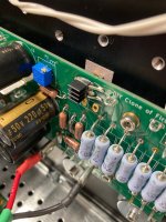
Yes. So I put some on my LUs as well with thermal adhesive tape, they're little and look like this.I used those little glue-on heatsinks for some CCS daughter boards in my Torpedo 3. They definitely help.
Before the stick-on heat sinks were there I was obsessively measuring the temperatures of the LUs during normal operation, playing music with the case open. They would routinely 'breathe' between about 47C and 61C case temps, measured with an IR temperature gun-thing, with the two channels not always at the same point in their temp cycles. Once I put on the little heat sinks, they were more consistently in the low to mid 60's. This seemed to be a paradox at first but if the increasing Rds(on) with increased temperature was self-limiting the bias, causing the 'breathing', then maybe the heat sinking decreases the magnitude of the temp swings? Anyway I think this was a good mod and I'm ready to put the lid on the case.
BTW I can't get over how good this amp sounds. It is completely another level from anything else I've ever heard in my system and it makes so much of my music sound new. It's actually moving at times. If you have the devices and the interest, I can't recommend an F3 clone enough.
Attachments
Ranshdow what voltage numbers did you end up getting I got 1v2,3v4,and 20v which is the closest I can get to 1v1,3v5, and 21v maybe my Lu’s got a little cooked soldering to the adapter and I need to change them out and just mount them to the heatsink with leg extensions to the board.
Before adding the little heat sinks, I got:Ranshdow what voltage numbers did you end up getting I got 1v2,3v4,and 20v which is the closest I can get to 1v1,3v5, and 21v maybe my Lu’s got a little cooked soldering to the adapter and I need to change them out and just mount them to the heatsink with leg extensions to the board.
LH board: TP1 21.23V, TP5 8V, TP4 3.51V, TP3 1.39V so Vds of 2.12V, on a device with a Vgs of -1.348 and a Vp of -1.77.
RH board: TP1 21.15V, TP5 8V, TP4 3.57V, TP3 1.37V so Vds of 2.2V, on a device with a Vgs of -1.353 and a Vp of -1.775.
Keep in mind this is after setting R3-R5 to 2R7, 2R7, and 3R3 for both channels.
I've suspected that these numbers might be related to the Vgs, which may be on the high side compared to the range mbrennwa reported for his LD1014D population in his GB. The ones for sale spanned from -1.375 down to -0.470 (!). Of course these devices were measured completely separately as part of the LU1014D group buy.
They were soldered from the underside and have nice concave, shiny joints. I don't think you need a barbell of solder all the way through a via to make a good joint. In fact I think I may have shorted a capacitor to ground doing that by accident earlier in this build.I would resolder those power resistors.
My understanding of the Aleph CCS bias point is that the ideal way to set it is with a distortion analyzer. I think slightly less than half of rail is preferable to greater than half of rail, so maybe okay, but I can't recall where I read that right now.Ranshdow. I can crank up r5 and get numbers pretty much the same as yours. is 21v really important? or would 20v work okay like I have it now
I suspect in that case the joint would have a resistive character and heat up, possibly leading to cracking and failure over time.O.K.
I've judged only what I've seen.
But what if metallized through hole from upper side is wrong to the bottom?
The barbell keeps the joint from rocking (with potential delamination of the tracks on the bottom).I don't think you need a barbell of solder all the way through
I'm fairly certain that in one case, I barbelled the positive lead of a capacitor enough to create a short to ground. At least, the charging character I noticed between circuit and test point ground on one channel went away when I desoldered that cap and cleaned things up.The barbell keeps the joint from rocking (with potential delamination of the tracks on the bottom).
The standard assembly technique for circuits with big MOSFETS around here is to attach them to heatsinks, align them under their PCB holes, then bend leads and solder from the top. Do people then unbolt the board and MOSFETs to inspect the undersides of these solder joints, and potentially resolder from the other side? I've built an ACA, a pair of MoFos, and now this F3 and I've never done that, personally.
Yes, I routinely do it on that way:Do people then unbolt the board and MOSFETs to inspect the undersides of these solder joints, and potentially resolder from the other side?
Fit the board and mosfets to the heatsinks with screws, without mica and goop.
Solder it on the top.
Then removing it, check the solder joint on both sides, resolder if it need.
Then refit, in this time with mica an goop.
On double-sided PCBs I soldering all parts on both sides.
I can't trust in metalized holes, even if I know, these are more reliable nowadays.
Must have to say, I using too much solder.
")
- Home
- Amplifiers
- Pass Labs
- F3 Builders Thread