I went with the schematic from post #25.
May I ask why the source resistor is 200R instead of 0R as the original F5?
And in that case, would you kindy point me to a place that I could read more about it?
Thanks.
May I ask why the source resistor is 200R instead of 0R as the original F5?
And in that case, would you kindy point me to a place that I could read more about it?
Thanks.
Post #25 is based on BL grade of 2SK246 / 2SJ103 with average 8mA Idss.
The source resistor in this particular configuration is part of the feedback network.
It gives you, together with R10 / R12, a nominal closed loop gain of 6.
For details please read F5 article of Nelson.
Patrick
The source resistor in this particular configuration is part of the feedback network.
It gives you, together with R10 / R12, a nominal closed loop gain of 6.
For details please read F5 article of Nelson.
Patrick
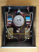
So, after a long time studying and building, I managed to complete my version of the F5 HA amplifier.
It's using Toshiba 2SK170 and 2SJ74 BL grade jfets and Fairchild FQP MOSFETs. I have biased the output MOSFETs at an idle current of ca. 200 mA, since I use both 300 and 32 Ω headphones. Power supply is dual mono, i.e. each channel has its own PS - the only common relation of the two is the primary winding of the power transformer. No regulation - just a CRC filter for each rail/channel (4 in all).
The chassis was bought from an ebay seller long ago. The heatsinks are more than enough for the set current - they just get mildly warm after an hour.
And, coming to the question "How does it sound?" the answer is: Fantastic, as any other F5 design.
Attached are 2 photos of my version.
And, in case you wonder what this connector is that I have used, I opted to use a 4-pin connector (with the relevant modifications on my headphones), since I wanted separate return paths for each channel (the only point where these two meet is at the central ground connection).
So, thank you EUVL for this simple, but wonderful design.
Regards,
Evangelos
Attachments

Lovely build! 🙂
I should learn from you to always use a generous sized enclosure. I often use a smaller one for my projects (I'm a cheapskate) and it usually results in a cramped, ugly and compromised layout.
I should learn from you to always use a generous sized enclosure. I often use a smaller one for my projects (I'm a cheapskate) and it usually results in a cramped, ugly and compromised layout.
Patrick,
There's not much activity here. I wonder where everyone went.
I have a bunch of Toshiba 2sk170/2sj74 V pairs that are all marked V. I test a few of the 170's, they come in at 13ma +/-.
I am looking for a project to use them in and found this one. I put together using the original schematic with my bench supply and got it working sort of. Can you suggest appropriate adjustments for the circuit with type V JFETS? I have a pair of audeze LCDX headfphones (20 OHMS) I'd like to built it for.
best wishes,
David
The only change required when using V grade is reduced drain resistors R3, 4.
https://www.diyaudio.com/community/threads/f5-headamp.271926/post-4270427
The exact value depends on the MOSFETs you are using.
And the MOSFET bias depends on your heatsinks.
I am using ~150mA for the MOSFETs, but 200mA is also OK with sufficient heatsinking.
Patrick
https://www.diyaudio.com/community/threads/f5-headamp.271926/post-4270427
The exact value depends on the MOSFETs you are using.
And the MOSFET bias depends on your heatsinks.
I am using ~150mA for the MOSFETs, but 200mA is also OK with sufficient heatsinking.
Patrick
Patrick,
How do i do this balanced? Somewhere back on this thread you mentioned it but i couldn't find the details?
David
How do i do this balanced? Somewhere back on this thread you mentioned it but i couldn't find the details?
David
https://www.diyaudio.com/community/threads/f5-headamp.271926/post-4718074
https://www.diyaudio.com/community/threads/f5-headamp.271926/post-4787408
https://www.diyaudio.com/community/threads/f5-headamp.271926/post-4789673
And he sold his commercial Gilmore (GSX) afterwards. 😉
Patrick
https://www.diyaudio.com/community/threads/f5-headamp.271926/post-4787408
https://www.diyaudio.com/community/threads/f5-headamp.271926/post-4789673
And he sold his commercial Gilmore (GSX) afterwards. 😉
Patrick


Similar data for my recently completed F5X preamp perfectly capable of driving headphones.
Loads are 10k, 500, 50 and 15 ohms.
Sounds great with my HE560 and HD650 phones😎
Loads are 10k, 500, 50 and 15 ohms.
Sounds great with my HE560 and HD650 phones😎
Attachments


Nic,
Your second figure should read 50ohm on the title and not 15 ohm ?
Great measurements. Many thanks.
The F5X Pre is of course never meant to drive low impedance loads (<600R). 🙂
Patrick
Your second figure should read 50ohm on the title and not 15 ohm ?
Great measurements. Many thanks.
The F5X Pre is of course never meant to drive low impedance loads (<600R). 🙂
Patrick
Yes - one of the graphs is incorrectly labeled.
My take of the F5X Pre has a buffered balanced line-out so I am actually also using it as an input selector for my BAL-DAO HA.
My take of the F5X Pre has a buffered balanced line-out so I am actually also using it as an input selector for my BAL-DAO HA.
FQP3N30 / 3P20 End of Life
In 2015, we have published curve tracings of the FQP3N30 / FQP3P20 complementary pair in TO220.
These are used quite widely, e.g. in Pass HPA-1, F5 HA, ACA Mini, BA3, etc.
https://www.diyaudio.com/community/threads/f5-headamp.271926/post-4363293
Just found out that they are now also end of life.
Digikey is only selling till stock last (445 pcs NMOS).
Mouser has 474 / 321 left.
Time to buy your lifetime stock.
Patrick
Last edited:
- Home
- Amplifiers
- Pass Labs
- F5 Headamp ?