Please read Nelson's article starting at the bottom of P.14.
https://www.firstwatt.com/pdf/art_f5_turbo.pdf
Cheers,
Patrick
https://www.firstwatt.com/pdf/art_f5_turbo.pdf
Cheers,
Patrick
I know this very well but I am still unclear what you want to say exactly? That wiring of two channels for balanced operation is different than two channels for single ended operation? Sure it is!Please read Nelson's article starting at the bottom of P.14.
https://www.firstwatt.com/pdf/art_f5_turbo.pdf
The diyaudio store F5Tv3 PCBs allow for wiring of the channels for balanced and for single ended as well
@starcat Perhaps clarify what you're asking again, please. What you described previously from post #1456, which Patrick quoted in #1459 is bridging. Then in post #1460, you say that you were not discussing bridging... but you were.
Also re: post #1460 - one amplifier board is not amplifying the positive half and the other the negative half of the signal. One board is amplifying a signal that is "in-phase", and the other is amplifying a signal that is "phase-inverted". See Dirk's previous explanation of differential in #1457.
I think you may be just mixing a few terms, but I cannot be sure. Maybe rephrase your question in a different way, and we can help. Dirk seems to have answered all the questions. What remains?
Edited for clarity re: differential. Removed phase reference to "input signal" to reduce confusion, and because it's not always phase inverted to the input (particularly when the input is already a differential signal)
Last edited:
With halves I meant the in-phase and phase-inverted signal of the same channel, i.e. differential.@starcat Perhaps clarify what you're asking again, please. What you described previously from post #1456, which Patrick quoted in #1459 is bridging. Then in post #1460, you say that you were not discussing bridging... but you were.
I refer to pos and neg signal as this is what the markings on the XLR are, hot, cold, plus and minus.
I guess the technically correct term would have been phase and phase-inverted.
I was thinking all time balanced and mentioned 4-channel equipment, signal not touching ground, etc, which to me points to balanced architecture, again sorry for any confusion. While pos and neg half is used with bridging as well, I never had any need for bridging as I am not amplifying for the superbowl
I don't own or use anything that is not balanced, even my headphones or headphone amps regardless if for electrostatics or dynamics, sand or valve based are balanced.
Cheers, all good and all questions answered
Hi all,
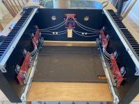
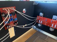
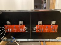
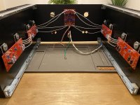
I’m making progress on my monoblocks and took a few pics to share and see if anyone saw any mistakes with the wiring between the front end and P/N channels before soldering.
Thanks!
I’m making progress on my monoblocks and took a few pics to share and see if anyone saw any mistakes with the wiring between the front end and P/N channels before soldering.
Thanks!
Attachments
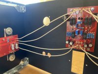
May I ask, are you not concerned about EM pick-up fly the front end board from the AC IEC input module? The front end board in your build is located very, very close to the body of the IEC module.Hi all,
I’m making progress on my monoblocks and took a few pics to share and see if anyone saw any mistakes with the wiring between the front end and P/N channels before soldering.
Thanks!
I've been contemplating using the 5RU chassis as you used, but mounting the front end board on a platform above the PS board with a steel shield of some sort. After seeing your configuration, I am interested in your thought process that led to the location you selected.
Reference my pics in post 1435. My fe board is above the iec inlet and both my amps are deathly quiet. As long as you are about an inch above, should not be a problem. Also, most logical place since you want To be as far away from tranny as possible. Wire routing will be more important. One thing I did differently, which may give you another option, is that the +/-V and ground wires on my build connect to output boards directly from ps. This also allows those wires to be draped low in the chassis and away from binding posts and ac.
Since you have empirically determined it works, that is great and I will follow your approach! It does save me lots of headache in figuring out internal placement. I am going to use a speaker protection board as well so real estate is precious. I was planning to mount my transformer vertically at the front end of the chassis using a home-made bracket of 1/4" aluminum angle with one leg at 4". I think that orients the EM field vertically (as I understand it), and minimizes its intrusion into the rest of the interior volume.Reference my pics in post 1435. My fe board is above the iec inlet and both my amps are deathly quiet. As long as you are about an inch above, should not be a problem. Also, most logical place since you want To be as far away from tranny as possible. Wire routing will be more important. One thing I did differently, which may give you another option, is that the +/-V and ground wires on my build connect to output boards directly from ps. This also allows those wires to be draped low in the chassis and away from binding posts and ac.
Halauhula, I don’t want to discourage you from trying to mount fe board on tall standoffs above psb. It’s actually a neat idea and could result in shorter, more direct wiring. I was merely pointing out that back panel did not create any noise issues for me, so it definitely “works”. I recall seeing other builds with same back panel mounting while reading through both f5t threads during my build. Best of luck
Understand. Creating a platform, however, has its own set of issue so it is nice to know that an easier alternative exists! Thank you so much for your information.Halauhula, I don’t want to discourage you from trying to mount fe board on tall standoffs above psb. It’s actually a neat idea and could result in shorter, more direct wiring. I was merely pointing out that back panel did not create any noise issues for me, so it definitely “works”. I recall seeing other builds with same back panel mounting while reading through both f5t threads during my build. Best of luck
Hello Halauhula,
hello algg,
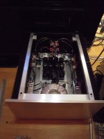
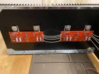
I never had a problem with my F5T-Monoblocks and the frontendboards above the AC-power-inlet.
O.K., my frontendboard is 'flying' horizontally above...
And I also have pretty long wiring from the FE-board to the N- and P-channel - boards.
My experience.
Cheers
Dirk
hello algg,
I never had a problem with my F5T-Monoblocks and the frontendboards above the AC-power-inlet.
O.K., my frontendboard is 'flying' horizontally above...
And I also have pretty long wiring from the FE-board to the N- and P-channel - boards.
My experience.
Cheers
Dirk
Attachments
Thank you for sharing your empirical experience as well!Hello Halauhula,
hello algg,
I never had a problem with my F5T-Monoblocks and the frontendboards above the AC-power-inlet.
O.K., my frontendboard is 'flying' horizontally above...
And I also have pretty long wiring from the FE-board to the N- and P-channel - boards.
My experience.
Cheers
Dirk
Would also recommend ditching the diodes. I was really hung up on this until better minds convinced me the amps are more stable without. i left them out and can confirm these things are dynamic as hell without them. Unless you have some really unique load, I don’t think you will miss them and increases your chances of successful build dramatically.
Thanks algg. Not sure if it matters if one removes the thermistor closest to FE on both the P&N channels. Does my illustration look correct?Edwinjones4, it looks like you have thermistor and it’s associated resistor on each output board. There should be only one thermistor per side (one for nchannel and one for pchannel), even with multiple output boards daisy chained.
Attachments
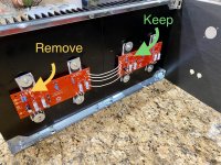
Like this?Would also recommend ditching the diodes. I was really hung up on this until better minds convinced me the amps are more stable without. i left them out and can confirm these things are dynamic as hell without them. Unless you have some really unique load, I don’t think you will miss them and increases your chances of successful build dramatically.
Attachments
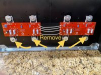
I removed the diodes and 1 thermistor per side; however, I unintentionally removed the thermistor from the boards closest to the FE board…instead of the boards furthest away. Does it matter? Same thing for R11 on the P channel and R12 on the N channel (see pics below).
Attachments
Ideally each of the 4 devices will see the same current and will be the same temp on the sinks. You're using one as "the representative" of the bunch.
tl;dr - I don't think it will matter, but I'd also like to have one more person chime in to be sure that I'm correct.
You currently have a gap between your sinks. It may close up at final assembly. You can (optionally) squish a little thermal compound between them for better thermal transfer if you want to go 'overboard'.
- Home
- Amplifiers
- Pass Labs
- F5Turbo Illustrated Build Guide