Thank you all for the attention and suggestions!
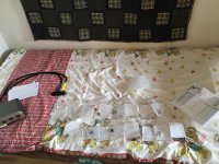
So, I've found these:
(QUAD 22)
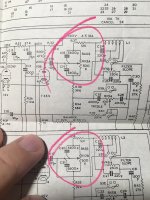
for C5 C6 C10 C11 - a Substitute of 25uF 16V
for C34 C35 - Substitute 0.022uF 160V
for C8 C9 - Substitute 0.47uF 250V
for C16 C17 -Substitute 0.1uF 400V
for C3 C4 -Substitute 0.1uF 160V
for C7 C12 C15 -Substitute 16uF 400V
for C18 C19 C20 - Substitute 5000pF 50V
for C22 C23 C28 C29 - Substitute 3900pF 50V
for C30 C31 - Substitute 1500pF 50V or 1500pF 200V
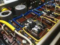
Mainly, I am not sure of the voltage ratings are right; especially for those little Styroflex caps at the tone controls (50VDC is enough?)
for QUAD IIs I ordered NOS Russian PIO's, as it's a recommended by so many forumers; the 0.1uF 400V and 0.1uF 160V the closest value to the original.
What do you think?
Don’t forget about the resistors. Some were out of spec. You probably don’t need to worry about the pink wire-wound ones, but the carbon composition ones need to be checked.
When ordering new resistors, check the voltage ratings. I forgot to do that and had to re-order new ones!
When ordering new resistors, check the voltage ratings. I forgot to do that and had to re-order new ones!
Contrary to what is stated above somewhere, you need a Tape adapter in a 22. Everything goes through it. You can get them on e-bay with a gain control pot, which is rather clever.
You don't need to strip and replace everything. The main resistors to look at are the ones directly connected to the can capacitor, including a 47K connected by a blue wire. Don't change the long pink ones, they are ageless. Also change the two 1.5M screen resistors over on the right. Change all four electros and all the film caps on that side and the two large ones on the top side, one rather inaccessible. I price renovating the tone controls separately, as a lot of customers don't care about the tone controls, they use Cancel. Think about that. Don't change any polystyrene caps, they are also ageless.
You don't need to strip and replace everything. The main resistors to look at are the ones directly connected to the can capacitor, including a 47K connected by a blue wire. Don't change the long pink ones, they are ageless. Also change the two 1.5M screen resistors over on the right. Change all four electros and all the film caps on that side and the two large ones on the top side, one rather inaccessible. I price renovating the tone controls separately, as a lot of customers don't care about the tone controls, they use Cancel. Think about that. Don't change any polystyrene caps, they are also ageless.
Thank you for your help agankinson and ejp!
I am sorry for my lack of knowledge in things, but I am not sure, how to check the resistors. Should I remove one leg to measure the values, or these could be checked in situ? Which voltage rating would be fine for these? And can you suggest a manufacturer?
For the adapter ejp, you mean something like this?
Yes, I overrunned one black capacitor, that is almost inaccessible for me (C17), and a drop-like resistor, that is somewhere under the button-matrix, and between the chassis (C2)
You can check the resistors with your multimeter. Typically they start getting out of tolerance — they should be +/- 10% I believe. So if you have a 1k resistor and it reads anything above 1.1k, change it.
You can usually measure them in-circuit. If you see that your multimeter looks like it’s unstable and the numbers fluctuate, it means there is a capacitor in parallel. Then you can just lift one leg of the resistor to check it.
The voltage ratings are based on how much voltage the resistor could see; exactly like a capacitor. I usually look for >500v ones, though, since overspeccing them doesn’t matter, and it’s much harder to find the voltage rating of a resistor after you have bought it.
Any good manufacturer will do; anyone on mouser would probably be fine.
The “mic” input does not require the adapter.
Don't bother. Just replace them. The ones I mentioned. Voltage rating 300V. 1/2 watt will do everywhere in a 22.I am not sure, how to check the resistors.
For the adapter ejp, you mean something like this?
Yes, that's the one.
I have a pair of Quadll with preamp and stereo tuner. Anybody interested? Should be picked up in The Hague. Plse send pm.
I am aware that this may open a debate, but which type of resistors do you suggest? Carbon composition or metal film (or carbon film) for substitution?
I saw at Mouser, that there are a lot of types, there is these 'Kamaya' carbon composition ones, those are probably make their resistors look authentic vintage, but I don't know it's a snake oil or not.
I would rather stay with some Vishay's.
What do you think?
The two 1.5MOhm resistors are almost in specs, one is 1.68, the other one is 1.72
I will check the others soon
When you attack the driver board, I found that the tags were quite brittle, so you have to be careful with the solder sucker or you can knock one off. Also it is more cramped in there than it looks! I rewired the OPT for 8 ohms, and fitted separate cathode bias resistors, and it is quite tight.
It will be a fun winter project!
It will be a fun winter project!
Metal film are generally better than CC. They are less susceptible to variance due to moisture and heat.
Vishay is good. Ohmite, Holsworthy, etc. you can’t really go wrong. If you really want to spend a lot of time reading about the differences you can spend days on it, but it’s less time actually buying and fixing the thing. ( I speak with some bit of experience here, sadly)
Speaking of experience, and since you indicated that this would hopefully not go into the winter: I tried to get two different 22s working. I spent the better part of a year with two perfectly good IIs not running while I tried to get the 22 working. Both were recapped and redone, but in the end the volume pot was just awful in both, and they are mostly unobtanium. I eventually gave up and got a passive volume control, and hooked the IIs up directly. Now I can listen to music through the IIs and while I wait for parts to come in to fix the 22s.
You might find yourself in a similar situation. I totally get where you’re coming from; The 22 is a really nice piece to have in a full setup, but in my experience I should not have made it a blocker to actually using the IIs while sorting it out. It can be finicky to fix and not really necessary with modern sources. The eq caps alone took a couple evenings!
Last edited:
I read somewhere that if you dont’t like the way you get there; then you probably won’t have much pleasure in the finished thing. I hope, that I will have the patience and with your help the knowledge to fix these beautiful piece of old electronics. If not, then I contact with a local professional to sort it out.
As I read at this subtopic, voltages in these could be lethal, so oc. I’ll take this into consideration.
Reading your suggestions and info from respectable fan of these, It looks quite straightforward. Oc, it will comes down to the very practice of doint the swaps.
Swaps, as I can only do swaps and maybe check voltages here and there.
We will see if replacing capacitors and some resistorts will help the project work out fine
As I read at this subtopic, voltages in these could be lethal, so oc. I’ll take this into consideration.
Yes, please do! Always observe the one-hand rule: In a piece of equipment that is on, never stick two hands in the equipment, for any reason. Hold the probe with one hand, and sit on the other, or put it in your pocket. You want to prevent any electrical current from going across your chest.
- Home
- Amplifiers
- Tubes / Valves
- Finally: The QUAD II and QUAD 22


