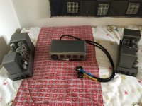
Beautifully and sympathetically done!
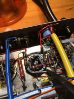
The tar under the capacitor is the potting compound from the mains transformer - at some point in the past it has got a bit hot, so the tar has melted. How is the other one? If they are similar then it is probably just from being on for a long time on a hot day.
The tar under the capacitor is the potting compound from the mains transformer - at some point in the past it has got a bit hot, so the tar has melted. How is the other one? If they are similar then it is probably just from being on for a long time on a hot day.
The other one’s clean. As far as I know, these were ,,used off” the 22 preamp and there were an AM tuner also in the cabinet.
The coupling capacitors are quite critical since if they are defective (leaky), grid current can flow, affecting the bias and excessive dissipation can result, causing the power transformer to get hot.
It is a good insurance policy to replace old capacitors. It is not a lot of leaked tar, so probably no big deal.
It is a good insurance policy to replace old capacitors. It is not a lot of leaked tar, so probably no big deal.
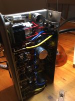
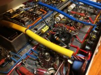
The can capacitor arrived on Thursday, and had time today to fit it into the unit.
This is it:
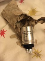
I had to enlarge the hole that took almost an hour to not to break anything, and I had this tool only... The hole was 15,5 and now it's 19 mm. The cap pack is 18mm diameter at the thread.
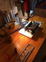
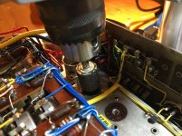
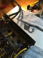
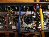
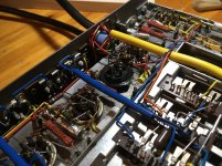
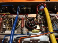
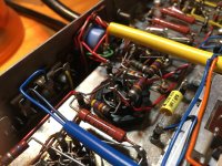
I soldered everything back, this time using the original resistors, and finally, powered them up
(of course, with fingers crossed and my other hand at the switch button)
Fortunately, this went extremely well, produced a very good sound on the test speakers (2+2 8 Ohm cheap speakers wired in serial)
I can easily say that I am veeery lucky as the switchpot works well in this 22, and nothing soldered in a wrong fashion. I only had to put in a new bulb into the unit, as the original's wolfram was torn.
However, I noticed that the left side produced some kind of a hum (check this video)
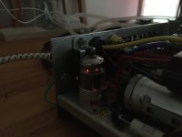
I've swapped the two monoblocks, and the hum stayed the same side, so I focused on the 22 and turned out that if I swap the two ECC83's the hum swifts.
Could this be only a faulty ECC83 then? I am not sure, as I heard a 'toasted' tube once in my Dynaco, but could this be it? The hum does not getting stronger if I turn the pot, and only heard when the voulme is at the lowest.
Now, I think it's time for measurements, I need some clues how to do that and where. I already have a doc.
This is it:

I had to enlarge the hole that took almost an hour to not to break anything, and I had this tool only... The hole was 15,5 and now it's 19 mm. The cap pack is 18mm diameter at the thread.


I soldered everything back, this time using the original resistors, and finally, powered them up
(of course, with fingers crossed and my other hand at the switch button)
Fortunately, this went extremely well, produced a very good sound on the test speakers (2+2 8 Ohm cheap speakers wired in serial)
I can easily say that I am veeery lucky as the switchpot works well in this 22, and nothing soldered in a wrong fashion. I only had to put in a new bulb into the unit, as the original's wolfram was torn.
However, I noticed that the left side produced some kind of a hum (check this video)
I've swapped the two monoblocks, and the hum stayed the same side, so I focused on the 22 and turned out that if I swap the two ECC83's the hum swifts.
Could this be only a faulty ECC83 then? I am not sure, as I heard a 'toasted' tube once in my Dynaco, but could this be it? The hum does not getting stronger if I turn the pot, and only heard when the voulme is at the lowest.
Now, I think it's time for measurements, I need some clues how to do that and where. I already have a doc.
Attachments
Last edited:
Nemeske, wonderful thread...and very timely as I've just bought a pair of Quad IIs that are in need of some gentle restoration. Looking at your thread you are doing exactly what I aim to do.
I have emailed Keith about the C4 and C6 capacitor box, just stumbled on that tonight on his site. I see your using it too...looks very simple to fit.
I saw your links to the 0.1uF caps on eBay. I was thinking of the same way, metal cased for C2 and C3, and the green PIO for C1, and probably a standard electrolytic for C5, whilst upping R12 (180R) to a higher power handling. Though I have read a few posts on splitting the resistor to one per KT66.
Dear chiily,
I received a very good guide here how to recondition these, although I am no expert at all. Keith was also very helpful and he gave a nice hint where can one's buy a triple can pack for the 22, and also made those cans for the II's
He even supplied me some styroflex caps and resistors for the tone controls that I rarely use, but when I turn the filter pot, it works as QUAD's intended to.
As for the smoothing and reservoir pack in the IIs, Keith uses higher values in spite of the factory specs, but everybody's telling me that those are fine. Funny thing is that I ordered those before the originals were sent out to my friend to check them if they are still ok. I received the substitutes from Keith, and already powered the amps up with them when I got the TCC's back. Miraculously, they were fine, leaking is negligible, ESR's good, and my friend have it well reformed.
Anyway, I left those new packs in the amps as they are fine, and I am more comfortable knowing that there are no 60 years old electrolitics in the power amps those could go wrong in any time.
Splitting the k-b resistors is probably a good idea for preserving those scarce KT66's, but I wanted as minimal change to the original circuit as possible. The system's working fine since October without distortion and noise however I even left all the original cc resistors in place. I do not know if this is a good idea for the future, still haven't measured any voltages, but now, it's dead quiet idle, and sing when it plays!
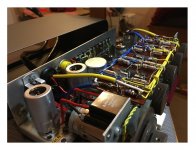
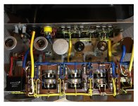
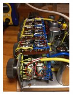
Styroflex caps in the tone control matrix received from Keith:


Nemeske,
Not sure how far you have got with replacing resistors in your Quad II. But I was wondering if we could compare notes on values? The following is list of resistor values taken whilst the resistor is in circuit and with no valves in the cct either.

R11 is set to N/A because I'm sure that is one that can't be measured in cct.
R4 is very high, but constant across the two amps (serial nos 77885 and 78079). Though most have wandered out of spec and should be replaced in a perfect world, especially R5, R6 and R10.
Just wondered if you had measured the ones in our Quad IIs
I've ordered the PSU cap box from Keith, on its way, and a tubes set from Watford Valves as my amps didn't come with any valves.
Work so far...
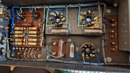
Not sure how far you have got with replacing resistors in your Quad II. But I was wondering if we could compare notes on values? The following is list of resistor values taken whilst the resistor is in circuit and with no valves in the cct either.
R11 is set to N/A because I'm sure that is one that can't be measured in cct.
R4 is very high, but constant across the two amps (serial nos 77885 and 78079). Though most have wandered out of spec and should be replaced in a perfect world, especially R5, R6 and R10.
Just wondered if you had measured the ones in our Quad IIs
I've ordered the PSU cap box from Keith, on its way, and a tubes set from Watford Valves as my amps didn't come with any valves.
Work so far...

Resistors are cheap, and yours looks like they're mostly out of spec. There's not really any point in keeping the old ones.
Remember to get new resistors that have the correct voltage rating! I made the mistake of ordering 300V parts, and then had to re-do it when I realized my error.
Remember to get new resistors that have the correct voltage rating! I made the mistake of ordering 300V parts, and then had to re-do it when I realized my error.
Dear chiily,
Sorry for the long delay, still have to get used to the new layout of the forum (I haven't received any notifications, that is strange... anyway.)
Quite a chart you got there! Certainly, I measured mine back when I was working on them, and yours look way better than mine.
To be frank, I did not bother replacing the resistors in the II's nor in the 22's. It takes almost no time compared to the harder part (those were the capacitors), but I do not want to struggle with them for now.
Maybe I am wrong and crazy (and my analogy's bad), but I simply did not want to make the ship of Theseus. I will see how this work out for now, and maybe swap those are required in the close future. (I've already stored some nice blue colored metal film Vishay's in my desk for the purpose, with overrated voltage for an authentic fit)
In this pair I have, the values are:
So, as you can see, these are mostly out of specs, but I have measured them cold, so probably these aren't real values as those may get a bit hot, and drift to a lower value (I am not sure).
IMHO you better listen to ahankinson or to the other professionals, they are probably talking of the swap for a very good reason.
Keith's pack will be very easy to fit, you just have to have the correct tools to remove the tagboard, and carefully align it back. You do not have to overtighten the nuts on the opposite side. You just want to turn them as much as the capacitor pack does not wobble.
May I ask which brand of tubes have you ordered?
Sorry for the long delay, still have to get used to the new layout of the forum (I haven't received any notifications, that is strange... anyway.)
Quite a chart you got there! Certainly, I measured mine back when I was working on them, and yours look way better than mine.
To be frank, I did not bother replacing the resistors in the II's nor in the 22's. It takes almost no time compared to the harder part (those were the capacitors), but I do not want to struggle with them for now.
Maybe I am wrong and crazy (and my analogy's bad), but I simply did not want to make the ship of Theseus. I will see how this work out for now, and maybe swap those are required in the close future. (I've already stored some nice blue colored metal film Vishay's in my desk for the purpose, with overrated voltage for an authentic fit)
In this pair I have, the values are:
| R2 was 1,32M and 1,1M where | R3=1,19M and 1,09M |
| R5= 187,2k and 220k | R6=194,4k and 200k |
| R4= 663 and 725 | R7=770k and 800k |
| R10=x | R8=3,17k and 2,86k |
| R11=x | R9=680k and 690k |
So, as you can see, these are mostly out of specs, but I have measured them cold, so probably these aren't real values as those may get a bit hot, and drift to a lower value (I am not sure).
IMHO you better listen to ahankinson or to the other professionals, they are probably talking of the swap for a very good reason.
Keith's pack will be very easy to fit, you just have to have the correct tools to remove the tagboard, and carefully align it back. You do not have to overtighten the nuts on the opposite side. You just want to turn them as much as the capacitor pack does not wobble.
May I ask which brand of tubes have you ordered?
I did replace a few resistor that were out of spec and left the rest:
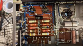
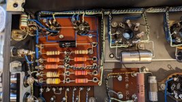
I removed the old C4/C6 capacitor box, replacing them with Keith's. And there was no tar leaking from under the transformers 🙂
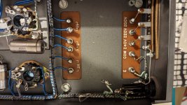
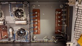
And with Keith's box fitted:
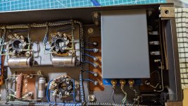
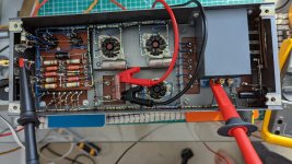
Valves wise I bought a pair of Harma GZ32 rectifiers, four Mullard NOS EF86s and a matched quad of GEC replica KT66s from Watford valves (https://www.watfordvalves.com/product_detail.asp?id=5942)
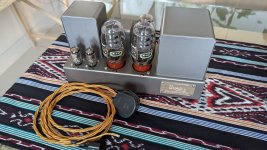
The measured HT is around 360VDC after the inductor (Keith's box adding a touch I think), but about 26.5VDC over R12, about 147mA on the KT66s.


I removed the old C4/C6 capacitor box, replacing them with Keith's. And there was no tar leaking from under the transformers 🙂


And with Keith's box fitted:


Valves wise I bought a pair of Harma GZ32 rectifiers, four Mullard NOS EF86s and a matched quad of GEC replica KT66s from Watford valves (https://www.watfordvalves.com/product_detail.asp?id=5942)

The measured HT is around 360VDC after the inductor (Keith's box adding a touch I think), but about 26.5VDC over R12, about 147mA on the KT66s.
Dear Chiily,
What to say, I think you've done a beautiful work.
I checked the company who sold you the tubes, and I think the price is very reasonable for a set of 10 tubes. I've never seen these KT66 replicas, even the sticker looks authentic to the original G.E.C tubes. I think, the resemblance is high between those Marshall KT66's (those are maybe chinese Shuguang tubes?).
Do you have the 22 control unit? If not, I think a bit modification's still needed on the input Jones plug (if I am correct, you should put a coupling cap there) but you better ask those with much more knowledge!
Nemeske thanks for you kind words, I'm just trying not to ruin the inside of a neat, classic amplifier. Everything I've done so far is reversible, not that putting back out of spec resistors and leaking, dried out capacitors is something that I will do myself.
I don't have a 22 control unit, my pair of Quads are fed from a miniDSP 2x4 HD, so I can easily integrate a sub into the ESL57s. And I haven't put a coupling capacitor in the signal path, mainly because the two previous amps I built and used didn't have one either, and the miniDSP is pretty well behaved.
I did take a few voltage measurements this afternoon after an hour's soak test of each amp.

I did this because I was concerned about the high B+ voltage and that can over bias the KT66s (anything about and over 28VDC on R12). And certainly my voltages are higher than those in the original cct diagram @ 330/340VDC. I did a little reading about a high B+, knowing that Keith's boxes can add to the B+ voltage, and it appears that the problem is probably linked to the main voltage back in the 1950s and/or the use of an analogue AVO meter who's lower impedance than a modern DMM's would pull the measured HT voltages lower. The important point is that the voltage over R12 is not excessive. Though I am considering splitting the cathode resistor in to two networks just to stop the KT66s damaging each other. But I'll try with the single resistor/cap network for the moment, get to know the sound, swap to a split network and listen again.
A daytime picture...
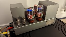
I don't have a 22 control unit, my pair of Quads are fed from a miniDSP 2x4 HD, so I can easily integrate a sub into the ESL57s. And I haven't put a coupling capacitor in the signal path, mainly because the two previous amps I built and used didn't have one either, and the miniDSP is pretty well behaved.
I did take a few voltage measurements this afternoon after an hour's soak test of each amp.
I did this because I was concerned about the high B+ voltage and that can over bias the KT66s (anything about and over 28VDC on R12). And certainly my voltages are higher than those in the original cct diagram @ 330/340VDC. I did a little reading about a high B+, knowing that Keith's boxes can add to the B+ voltage, and it appears that the problem is probably linked to the main voltage back in the 1950s and/or the use of an analogue AVO meter who's lower impedance than a modern DMM's would pull the measured HT voltages lower. The important point is that the voltage over R12 is not excessive. Though I am considering splitting the cathode resistor in to two networks just to stop the KT66s damaging each other. But I'll try with the single resistor/cap network for the moment, get to know the sound, swap to a split network and listen again.
A daytime picture...

There's quite a discussion here about the same measurement.You must have interchanged your plate and screen measurements. Those values are impossible.
https://www.vintage-radio.net/forum/showthread.php?t=57683
I'll try to remeasure tomorrow with the additional measurements in the link.
I would look to at least swap out R7 and R9, the 680k ones. These are the grid leak resistors and at 680kR they are a bit bigger than the KT66's spec sheet recommendation of 500kR, so having them go higher is probably not a good idea.Dear chiily,
Sorry for the long delay, still have to get used to the new layout of the forum (I haven't received any notifications, that is strange... anyway.)
Quite a chart you got there! Certainly, I measured mine back when I was working on them, and yours look way better than mine.
To be frank, I did not bother replacing the resistors in the II's nor in the 22's. It takes almost no time compared to the harder part (those were the capacitors), but I do not want to struggle with them for now.
Maybe I am wrong and crazy (and my analogy's bad), but I simply did not want to make the ship of Theseus. I will see how this work out for now, and maybe swap those are required in the close future. (I've already stored some nice blue colored metal film Vishay's in my desk for the purpose, with overrated voltage for an authentic fit)
In this pair I have, the values are:
R2 was 1,32M and 1,1M where R3=1,19M and 1,09M R5= 187,2k and 220k R6=194,4k and 200k R4= 663 and 725 R7=770k and 800k R10=x R8=3,17k and 2,86k R11=x R9=680k and 690k
So, as you can see, these are mostly out of specs, but I have measured them cold, so probably these aren't real values as those may get a bit hot, and drift to a lower value (I am not sure).
IMHO you better listen to ahankinson or to the other professionals, they are probably talking of the swap for a very good reason.
Keith's pack will be very easy to fit, you just have to have the correct tools to remove the tagboard, and carefully align it back. You do not have to overtighten the nuts on the opposite side. You just want to turn them as much as the capacitor pack does not wobble.
May I ask which brand of tubes have you ordered?
The DCR of the choke is about 680 ohms. The DCR of the OPT primary is about 120 or 180 ohms depending which side you measure. Allowing for the different currents you will must get Vs < Vp unless there is something seriously wrong with the choke or the OPT primary.
I'm only coming at this from what I'm measuring on both amps. And both have Vs > Vp, as discussed in the link I posted, especially post #6 were GJ does get the same result. I did run through the additional measurements of that link for V-W, V-U,Y, Y-X, Y-Z and nothing look different from the link.The DCR of the choke is about 680 ohms. The DCR of the OPT primary is about 120 or 180 ohms depending which side you measure. Allowing for the different currents you will must get Vs < Vp unless there is something seriously wrong with the choke or the OPT primary.
I'm new to valves so excuse my ignorance, I may be talking rubbish...
Voltage before the choke is 366V, after 362V (on my amps), only a difference of 4V. However, the drop over Y-Z is 12.6V, making the plate 353.4 (366-12.6) making it less than the 362V for Vs.
As the resistance between Y-Z is about 176R there is about 72mA (12.6/176) in the OPT for V3, which is close to the 65mA in the schematic. For V4 the current is about 72mA (8.9/123). Again close to the schema value. Do they seem wildly wrong?
The voltage across R12 remains about 26.5V, where R12 is 180R.
I measured these with an 8R dummy load and nothing connected to the input.
Both amps measured about the same.
Looking at a marked-up schematic I have. here is around 130mA going through the DCR of the OPT, supplying both output tubes' anodes (65mA each), and 17mA for the screens and input tubes combined (14 mA for the screens), so a bigger voltage drop at the anode is not unreasonable.
I did fit screen grid resistors in mine, 100R I think. I have subbed tubes that are not KT66 and I wanted to be able to limit screen current, and hence screen dissipitation. Also with 100R it is very easy to measure the voltage drop and keep tabs on the screen current.
I did fit screen grid resistors in mine, 100R I think. I have subbed tubes that are not KT66 and I wanted to be able to limit screen current, and hence screen dissipitation. Also with 100R it is very easy to measure the voltage drop and keep tabs on the screen current.
I don't want to take anymore space in Nemeske's thread, so I did a little more measuring, documented here https://www.vintage-radio.net/forum/showthread.php?t=186994
GJ knows his Quads 🙂
GJ knows his Quads 🙂
- Home
- Amplifiers
- Tubes / Valves
- Finally: The QUAD II and QUAD 22

