Mmmm, without seeing your circuit - can't really comment. Your implementation might be different but as I understand the principal is that a sensor resistor somewhere in the o/p stage generates a voltage as the o/p current passes through it, this voltage is then sent to the I/P via a resistor that is chosen such that the additional resultant voltage rise at the input restores the voltage at the O/P to a level close to the no load Voltage.My F7 simulation says that if the source impedance Rgen decreases, then the DF increases.
However, the DF does not change too much")
Without resorting to spice, logic seems to dictate that the input can only be adjusted sufficiently if the prevailing impedance allows this to happen. In other words if the overall I/P impedance ( which includes the total R between the source O/P & the amp I/P ) is high it moves easily and if it is low it is does not move easily thus affecting the amp O/P either more or less respectively.
Perhaps your your circuit has a different principal of operation ? ?
Hi mikelm,
my circuit is based on topology 2 - see @Ihquam #442.
The simulation is the same as showed by @avdesignguru in #1710.
LT-Spice calculation of DF is done using {Rload} as parameter in
.step param Rload list 8 4
then the output impedance is given with the known formula:
Zout = 8ohm*(V(out+,out-)@1-V(out+,out-)@2)/(2*V(out+,out-)@2-V(out+,out-)@1)
and
DF = 8ohm/Zout
I hope that can make things clearer
Hegel had never affected a single nerve in my body positively, so no surprise there.Many thanks Nelson - that is food for thought.
Should make it relatively insensitive to whichever pre-amp is used
Strange then that Jay said it did not sound that great with Hegel as a Pre ( Perhaps it's was just the Hegel )
He said that everything else sounded great.
Hi ACnotDC,Hi mikelm,
my circuit is based on topology 2 - see @Ihquam #442.
The simulation is the same as showed by @avdesignguru in #1710.
LT-Spice calculation of DF is done using {Rload} as parameter in
.step param Rload list 8 4
then the output impedance is given with the known formula:
Zout = 8ohm*(V(out+,out-)@1-V(out+,out-)@2)/(2*V(out+,out-)@2-V(out+,out-)@1)
and
DF = 8ohm/Zout
I hope that can make things clearer
Thanks, I think this is just the way that DF is being calculated and the F7 design can make this confusing.
Adding in the Positive FB makes an amp with a highish O/P impedance amps behave as if it has a very low O/P impedance
But it doesn't. It's just a highish O/P impedance amp with more signal applied to the input when O/P current flows through the load.
So depending on how the DF calculations are arrived at, the results can be very different.
My calculations are simply based upon how much the O/P voltage drops when a load applied compared with the O/P voltage with no load.
Using this calculation method the DF can be increased to infinity & beyond
. . . . even though the actual O/P impedance is still quite highBeyond Infinity in this case means that when a load is applied the O/P voltage actually increases in which case the DF figures will become negative.
I have only just joined this thread so apologies is all this has been covered already.
It's OK, I'm Britishmikelm, there is no need to appologize.

I thought the best parts were kept in da shoe box on a top shelf in the shop.That is not where they are kept.

Ahhh, it's good to be back, I missed all of you.
Cheers
DOH!!I thought the best parts were kept in da shoe box on a top shelf in the shop.
Oh no - this is the way it went down:I thought the best parts were kept in da shoe box on a top shelf in the shop.
Ahhh, it's good to be back, I missed all of you.
Cheers
"On the wall in my lab is a little box with a glass window labeled: DANGER - POSITIVE FEEDBACK I broke the glass. Inside was a single resistor."

I'm planning a build of an F7 type amplifier and I'd be interested to hear if anyone has done a successful build using these high power Exicon Lateral Mosfets.
https://www.profusionplc.com/parts/ecw20n20-s
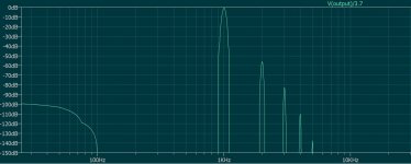
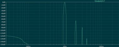
Spice predicts ( ) that this higher power type gives less significantly HD with the same FB & bias current compared with their less powerful 10N20 with only a very small phase margin trade off.
Would be interested to hear peoples thoughts on using these devices
thanks
https://www.profusionplc.com/parts/ecw20n20-s
Spice predicts (
) that this higher power type gives less significantly HD with the same FB & bias current compared with their less powerful 10N20 with only a very small phase margin trade off.Would be interested to hear peoples thoughts on using these devices
thanks
Last edited:
For this circuit higher transconductance will get you more open loop gain and more feedback
I agree - but because I wanted the FB in the finished amp to be fixed at quite a low level, I wanted to see how these devices compared in the circuit with same amount of feedback. So I deliberately adjusted the circuit in spice to make this comparison
And as you can see, spice predicts that even with matched feedback the 20n20 etc gives quite a lot less HD
So I was just wondering if there might be any downside to using the 20N20s ?
Because if not, to me the results with them look pretty good
Attachments
Last edited:
Member
Joined 2009
Paid Member
rightly or wrongly, I tend to trust Spice for comparative tests. Especially if the results are logical. These results seem logical so lets see.Are you sure the Spice models are that accurate? Does the distortion depends also on the speaker load?
Sure the load affects HD but this was just an indicative comparison.
Last edited:
I think you are on the right track trying the 20N20 and 20P20. Higher transconductance and they appear to be slightly more linear. Which Spice models are you using? This thread by @IanHegglun has the most recent and accurate ones I know of. Also, you can request "binned" versions from Profusion to get a closer match between N and P.I agree - but because I wanted the FB in the finished amp to be fixed at quite a low level, I wanted to see how these devices compared in the circuit with same amount of feedback. So I deliberately adjusted the circuit in spice to make this comparison
And as you can see, spice predicts that even with matched feedback the 20n20 etc gives quite a lot less HD
So I was just wondering if there might be any downside to using the 20N20s ?
Because if not, to me the results with them look pretty good
Last edited:
- Home
- Amplifiers
- Pass Labs
- First Watt F7 review