Thanks for your post. I am using the Hegglun models but have not yet checked if they are the latest versions.I think you are on the right track trying the 20N20 and 20P20. Higher transconductance and they appear to be slightly more linear. Which Spice models are you using? This thread by @IanHegglun has the most recent and accurate ones I know of. Also, you can request "binned" versions from Profusion to get a closer match between N and P.
It would be interesting to compare the 20N20/20P20 with a two pairs of the 10(x)20s because the behaviour of the 20(x)20s as far as I understand it, should more or less have the same effect, and the apparent extra linearity of the 20(x)20s might just arise from effectively sharing the current demands between multiple devices in the way that Nelson does in his Pass Labs amps. The 20(x)20s just being a more convenient way to achieve this. Please correct me if this is not the case.
I will try in spice and report back
As far as I understand the "matching" between the Exicon LMFs is only between ones of the same polarity to make paralleling more simple and the matching of upper & lower devices does not really concern me as I am not aiming to try and cancel the 2nd HD.
mike
I think you are on the right track trying the 20N20 and 20P20. Higher transconductance and they appear to be slightly more linear.
wtnh
OK, I tested 2 x 10(x)20s to see how it compared with the 20(x)20s in spice and found that the 2 x 10(x)20s @ 1.4 amps in total gave an almost identical FFT result as 1 x 10(x)20s @ 1.4A. So it would seem ( if we believe SPICE and the models ) that the 20(x)20 option is considerably more linear and would seem like an excellent candidate in an F7 type amp.Has anyone here made a balanced F7 type amp ?
The reason I ask is that I think I have noticed that as the FB is reduced on this kind of amp, some on the "characteristics" of the electrolytic caps in the PSU begin to reveal themselves. In a balanced version this would become common mode and cancelled out to some extent.
So I would be interested:
i) to hear if anyone had tried this and if so . . .
ii) to hear how the SQ compared to an unbalanced version.
thanks
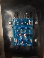
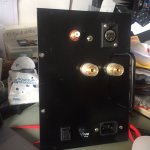
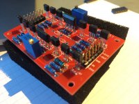
I have one in monobloc pending...but not yet tested...Has anyone here made a balanced F7 type amp ?
Attachments
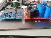
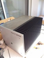
Looking goodI have one in monobloc pending...but not yet tested...
Ver
Very nice!!I need time to finish, too many projects pending...my UGS Preamp to finish too...
Yesterday, I did some impedance measurements of my 3-way, bass reflex, and 90 dB speakers using LIMP.
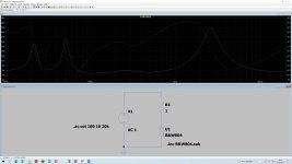
After saving the measured data in a CSV file, it is easy to make an LTspice model copying data into simple varistor (pic #1).
I was curious what happens when my F7 sim (like this in #1710) is loaded with this modeled speaker.
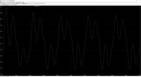
The following test with 10 kHz square wave made me think a lot. I didn't want to believe it could be so bad.
I could hardly see anything that seemed to be a square wave (pic #2).
The result of the next sim test with disconnected sense resistor from input was much better.
I could see a good-looking square wave with some overshoots (pic #3).
Question: Am I correct in assuming that my speaker is not suitable for the F7?
After saving the measured data in a CSV file, it is easy to make an LTspice model copying data into simple varistor (pic #1).
I was curious what happens when my F7 sim (like this in #1710) is loaded with this modeled speaker.
The following test with 10 kHz square wave made me think a lot. I didn't want to believe it could be so bad.
I could hardly see anything that seemed to be a square wave (pic #2).
The result of the next sim test with disconnected sense resistor from input was much better.
I could see a good-looking square wave with some overshoots (pic #3).
Question: Am I correct in assuming that my speaker is not suitable for the F7?
Attachments

Rsen is only one of three variables that defines the amount of Pos FB.I don't think so, Rsen is only 0.33 ohm
You can run AC sweeps in LT spice to with the load connected & disconnected to establish how much the input is increased when the load is connected.
BTW, just because the square wave subjectively might look horrible with that speaker connected it does not mean that the actually speaker will sound subjectively bad.
I know there are other parameters that affect the PCF. But Rsen is the main actor here.
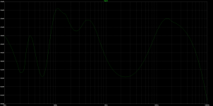
The PCF changes at the input of the FETs with the SPK at the output are as expected, (Pic #4).
Without SPK it is constant about -6dB up to 20kHz.
Why did I take all the measurements?
Because I'm not completely satisfied with the sound of my F7 clone with the speakers.
I have the impression that it lacks a little brightness. It's just too dull for me.
Maybe I'm too old?
Attachments
That's a fairly accurate description of almost any F-style amp bar the original, non-Turbo F5.I have the impression that it lacks a little brightness. It's just too dull for me.
The F7 is buttery smooth, but does roll off the top a bit. I like using a coupling transformer to make it a little more lively. Almost any 600:600 transformer will add a bit of zing without becoming harsh. You can adjust the termination to taste
This has nothing to do with the square wave behaviour though, which will continue to collapse as amplifier loses feedback at HF. The bandwidth is going to be limited with such simple circuits, that is a fact of life. It is not going to measure or simulate as well as a high-feedback design, but this may or may not be an important goal to begin with.
I don't understand those results in post #1848. All of the impedance peaks are lower than 10kHz and all the harmonics of a 10kHz square wave are significantly far away from and should not be affected by those impedance peaks. Those square waves should be looking significantly better if the load impedance is relatively constant above 10kHz.
[Schematic removed by moderation]
[Schematic removed by moderation]
Last edited by a moderator:
What series resistance have you added to the input of the F7 ?F7 clone is connected directly to the variable output of TEAC NT-505 with Rout = 150R. It sounds good on other amps.
Actually, might be better if you post your circuit diagram.F7 clone is connected directly to the variable output of TEAC NT-505 with Rout = 150R. It sounds good on other amps.
Your design seems to be close to the spirit of Nelson's design.OK. Here is my F7 sim. In the attachement you can find the complete sim as zip.
Have fun.
The one thing that jumps out to me a possible source of an amplifier that I would hate the sound of and that is the 3 trimmers in the I/P stage.
For my ears normal off the shelf trimmers are the worst sounding resistors I have ever heard ( with the possible exception of NTC Thermistors ) so if trimmers are really needed I arrange for the possibility of replacing the trimmers with fixed value once the correct values are established. I noticed the trimmers Nelson used look non-standard so they might sound nicer.
The other thing you could try is making the 39K series I/P resistor 4.7K / the positive FB resistor 100K, and the sense resistor 1.5R ( check these values in SPICE first for your design ) With values like this the rolling off of treble will be less - you might prefer the sound that way.
- Home
- Amplifiers
- Pass Labs
- First Watt F7 review