hdspeakerman,
There is software that can convert *.jpeg into FRD and ZMA files for using in crossover design applications:
need help using SPL TRACE to create FRD and ZMA files -
Techtalk Speaker Building, Audio, Video Discussion Forum
Maybe try it out and let us know if it works?
There is software that can convert *.jpeg into FRD and ZMA files for using in crossover design applications:
need help using SPL TRACE to create FRD and ZMA files -
Techtalk Speaker Building, Audio, Video Discussion Forum
Maybe try it out and let us know if it works?
Progress Slowed
My apologies to the folks interested in this project. I had amplifier problems and also health issues in my family. I got some guidance from John Hollander over at Parts Express on the preparation of the files needed for crossover work. We used Jeff Bagby's Blender and Response Modeler and I believe we have good files that I will post. I have tried to come up with a good crossover but I am not very experienced. Maybe someone here can make it work. I have listened to the speaker I built quite a bit and enjoy it, even with no crossover.
My files are .frd and .zma. I get a message that they are invalid. What do I need to do?
My files are .frd and .zma. I get a message that they are invalid. What do I need to do?
I think you can attach .zip files, so just put both into a folder and zip it up.
The box is 12 inches tall by 7 inches wide. The AC130f1 is centered and mounted 1 inch from the top of the cab. The distance from the top of the cab to the center of the AC130f1 is 4 inches. The FR58 is centered and its center is 4.5 inches from the bottom of the cab. The offset between the two drivers was 1.47 inches.
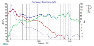
Using the files you provide above, here is my first cut at the XO, at a nice FAST frequency of 600Hz. I was not able to make it a transient perfect - as I had to invert the tweeter. However, that may have something to do with the drivers acting electro-acoustically like a 2nd order crossover despite being 1st order electrically. You can tweak it from here - but this would actually sound pretty good. I am not sure why the FRD has such a big peak at 170Hz as the AC130F1 is really quite smooth. The Xsim DXO file is uploaded as .ASC. Rename to .DXO to use in Xsim.
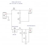
Schematic:

Frequency and Acoustic Phase:

Imepdance and Elect Phase:

Schematic:
Frequency and Acoustic Phase:
Imepdance and Elect Phase:
Attachments
Last edited:
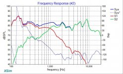
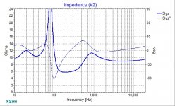
Here is a XO at 1kHz, which might give a little more power to be delivered from the woofer as a midbass. There is a high impedance peak near 90Hz that I have not dealt with yet... But here are standard Parts Express part numbers for all the components.
Schematic for 1kHz XO:

Freq Response:

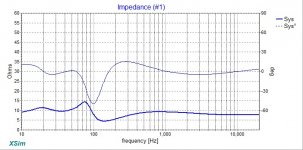
Impedance:

I have a question, what is your box alignment? Sealed or bass reflex? The peak at 170Hz might be result of too small a box and not enough damping.
Schematic for 1kHz XO:
Freq Response:
Impedance:
I have a question, what is your box alignment? Sealed or bass reflex? The peak at 170Hz might be result of too small a box and not enough damping.
Attachments
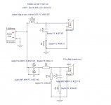
You can use the Dayton 3mH coil if desired, should not affect Xo too much.
Dayton Audio 3.0mH 18 AWG Perfect Layer Inductor Crossover Coil
Dayton Audio 3.0mH 18 AWG Perfect Layer Inductor Crossover Coil
- Home
- Loudspeakers
- Full Range
- FR58EX and AC130F1 micro-FAST / WAW