Always tradeoffs...
I'm quite happy with my arrays as you are or should be with yours, even more so with the new filters. As the sims show, even with driver to driver combing eliminated, there is still boundary reflection combing to deal with. Then there is the argument/discussion as to whether combing is audible in the first place.
Try some other architecture and you'll only spend a great deal of time and effort learning and optimizing its tradeoffs just to get back to where you were and perhaps a little further ahead. For some, me in particular, that would be fun but it does take one away from enjoying the music.
I have no real intentions to add a tweeter. The filtering I am adding is an experiment to see if I like it. As it presents better simulated results at every angle I look at it. Most specifically the clean up of the IR (as predicted).
Yes, I'm quite happy with my arrays (as they were) but I'm still trying to find the boundaries, so to speak. The listening room is the biggest hurdle towards great sound. Vituixcad has helped explain the experience, and even provides a partial answer of why these arrays are as clean sounding as they can be.
I could have stopped tinkering long ago. But I like to learn from it as well as enjoy the fruits. Even though I'm still busy adding the filters (sadly the weather over here doesn't help with that) the new list or round of experiments I want to try grew even longer. But I'll first have to create a (new) base or reference as my room as well as the arrays have changed.
So no tweeters for me in the foreseeable future. I merely added that tweeter here as an option to investigate. I know ra7 has been following and trying to figure out the more ideal expanded array. An other member here has run simulations with tweeters to possibly experiment with once he's ready for it. This thread has most of the possible schematics and simulation all in one thread. So it seemed the obvious choice to place this info here 😉.
I think my sims with the Beyma AMT looked quite good:
I'm sure even more could be done by carefully designing the filters.
I will have Beyma TPL-200/B arriving within a few weeks so I can update the sims with my own measurements.
I'm sure even more could be done by carefully designing the filters.
I will have Beyma TPL-200/B arriving within a few weeks so I can update the sims with my own measurements.
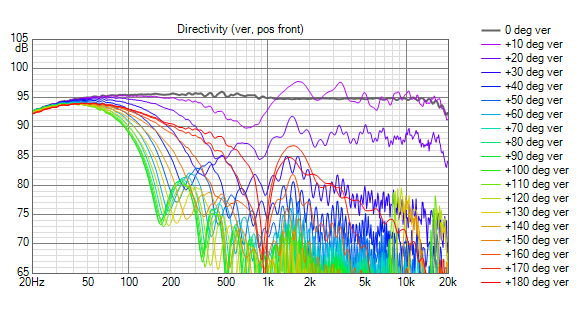
Yes the Beyma sim is quite good. The 10 degree of vertical line is impressively close to the on axis response - and then response drops off a cliff. That is the major difference with cone drivers, which degrade gradually as you move off axis. That is a 2-edged sword because no doubt that cliff in the response is responsible for the relatively small amount of floor and ceiling reflection combing visible in the room response curve.
That looks to me like seated only listening which is really the only kind of listening I do lately. (That didn't use to be the case.) Adding a horn to the TPL150 to make it a TPL200 is going to add to the center to center distance for the crossover, making it more vertical offset sensitive.
That looks to me like seated only listening which is really the only kind of listening I do lately. (That didn't use to be the case.) Adding a horn to the TPL150 to make it a TPL200 is going to add to the center to center distance for the crossover, making it more vertical offset sensitive.
Both TPL150 and TLP200 exists with or without the horn (/H suffix). The main difference between TPL150 and TPL200 is power handling (and maybe sensitivity) as I understand it.
In my sims I placed it in the midpoint between floor and ceiling, so the seated listening position (which is also the design axis in the sims) is actually about 5 degrees down from its on-axis. Standing position is about 15 degrees above design axis, which corresponds to the top line in the directivity plot (the others are 30 and 45 degrees).
I was considering the horned version before but as you say the c-c distance gets a lot bigger. Also, the horisontal dispersion seemed too narrow compared to the Vifas.
Thanks for the correction. I would use the 200 as you can likely get more low end at reasonable SPL from it.
Here is a pic from an Atilsey thread on TPL 3-way.
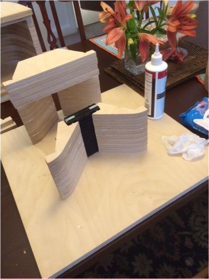
Atilsey did his own horn and it added almost nothing to the CTC
If I were doing this and cost/time were no object, I would run the glue lam baffle full height, driving the midbasses through slots so horizontal coverages would match.
Here is a pic from an Atilsey thread on TPL 3-way.
Atilsey did his own horn and it added almost nothing to the CTC
If I were doing this and cost/time were no object, I would run the glue lam baffle full height, driving the midbasses through slots so horizontal coverages would match.
Attachments

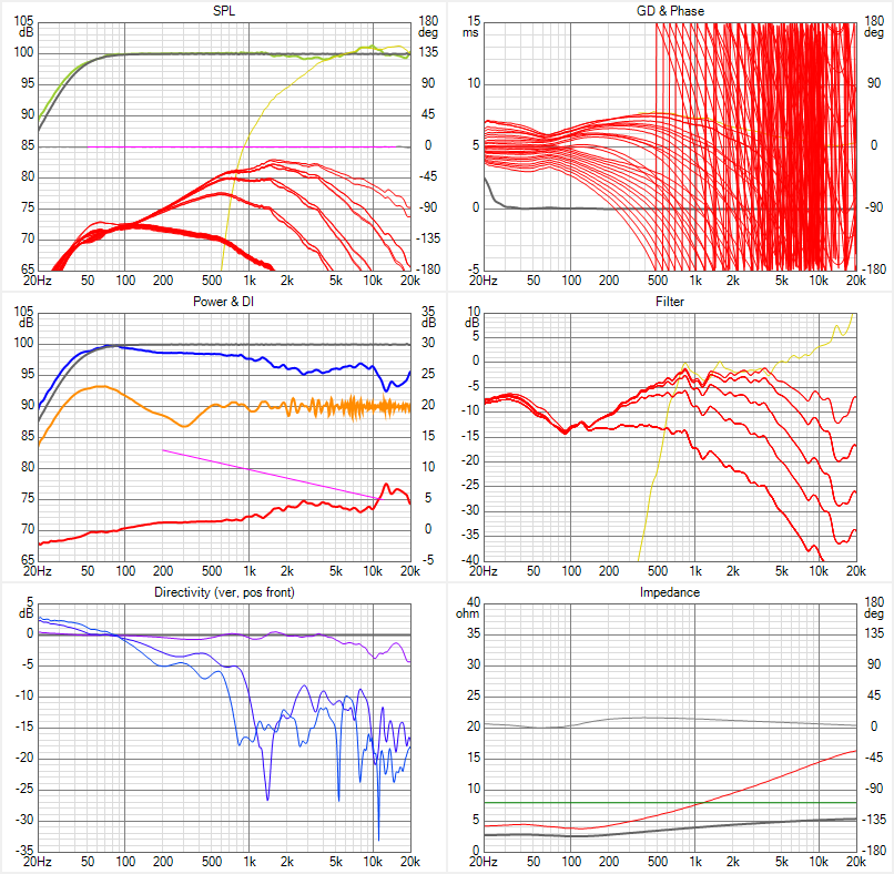
I stumbled across the Dayton PHT1-6 Planar Tweeter ($97) and thought it worth a look. It blended with the array quite well, likely because it is within a small waveguide. There is a lesson there.
Dayton Audio PHT1-6 Planar Horn Tweeter 6 Ohm
Here is the vituix response just swapping it for the SRT7 and re-equing
Dayton Audio PHT1-6 Planar Horn Tweeter 6 Ohm
Here is the vituix response just swapping it for the SRT7 and re-equing
Attachments

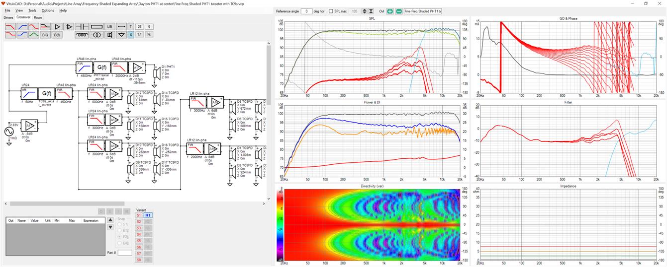
speaking of best results with waveguide in center, I'm going to repost an expanding array with waveguides in center. I'm sure I posted this before but I couldn't find it right away so I can't just point to it.
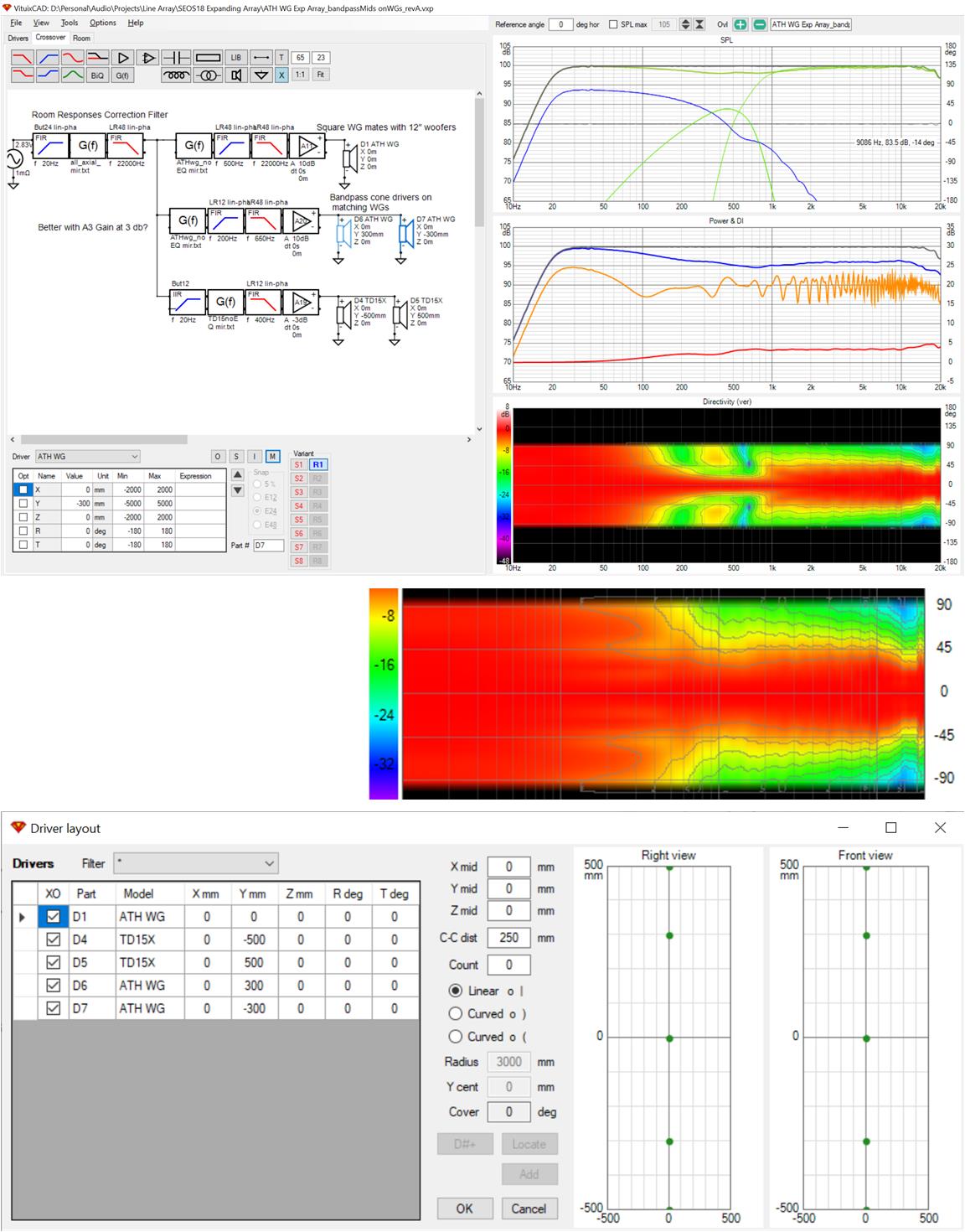
I took a square waveguide sized to match with 12" woofers from the ATH thread and traced its directivity. I assumed a 1.4" CD at center useable down to 500 Hz. I flanked this waveguide with two others immediately above and below and assumed them driven with cone midwoofers in the 200 Hz to 650 Hz range. These filled in the gap between the central CD and 15" woofers at top and bottom. Without the bridging drivers, the central wg loses pattern control early and lobs appear in the 500 Hz range. Despite my best(?) efforts I still got an abrupt directivity change at 1 KHz where the wg's lose pattern control
This wouldn't be a terribly extravagant approach if one was 3D printing his own waveguides. It might be that 12" woofers would work just as well as the two "extra" waveguides but I didn't try that.
Attachments

I'd want wider directivity in the vertical plane than the first sim shows and shallower than the second (previously posted) sim. Which is doable I guess if you make up your own waveguide, and use the arrayed drivers to steer that directivity for mid and bottom. Due to the center to center distance the side lobes start to form at higher frequencies, that's what I would want to prevent when a tweeter is added. Yet keep an even as possible vertical output for sitting and standing positions.
The width I have now, with my specific filters, works better than the unshaded array over the same bandwidth and that shows the in-room prediction (within that window) to be largely without floor and ceiling influence. In my personal hunt, that would be the goal of an expanding array like that.

But to even consider it, from my point of view, it would have to be both smooth in the vertical plane (over a controlled width of about a 15 degree angle) and in the horizontal plane (mimicking the results of a single driver there).
Purely to avoid the floor/ceiling as much as possible while retaining that flat response within the envisioned window.
The width I have now, with my specific filters, works better than the unshaded array over the same bandwidth and that shows the in-room prediction (within that window) to be largely without floor and ceiling influence. In my personal hunt, that would be the goal of an expanding array like that.
But to even consider it, from my point of view, it would have to be both smooth in the vertical plane (over a controlled width of about a 15 degree angle) and in the horizontal plane (mimicking the results of a single driver there).
Purely to avoid the floor/ceiling as much as possible while retaining that flat response within the envisioned window.
Attachments

Last edited:
Let me add something here...
I've been on a personal quest to get the cleanest shot at the direct wave front I could get, out there in my reasonably normal looking living room. That's why I opted for the arrays, as I saw that as a means to reach a goal. The damping panels were included as an idea from the start, as was the DSP treatment. This later addition is something I had been wondering about, back in 2011, when the arrays were just a thought in my mind. I had been going back and forth in my mind, trying to determine if a frequency shaded array would work, but I couldn't see it when I thought about the floor/ceiling reflections such a shaded array would encounter. The sims from Vituixcad, as started by nc535 finally gave more insight that brought some more clarity upon what the array really does within a room. So the filters I came up with are a prolongation of my personal quest. The quest that should prove to me what's important about being able to circumvent parts of the "room trouble" when trying to get great sound within a room.
But... and it's a big but... I am not sure, nor convinced yet that this route is "the way" to audio nirvana. As I see it, a waveguided speaker, be it a waveguide like we can now easily engineer with Mabat's tools or a variation on the Synergy concept might be a better choice than simply trying to avoid floor and ceiling reflections (like I'm doing here). While they (the reflections from such a horn) will alter the curve we perceive, that won't color the sound much, as the total average will still be in line with the direct sound, just try it in a Vituixcad sim.
So far, the road I've been upon has brought me a lot of joy, but I also needed to find other ways to deal with cross talk, for it became more obvious. I needed something to make up for that, to make the result shine. While maybe, just maybe, the reduced reflections one would get from a horn speaker or otherwise controlled directivity speaker helps hide things like cross talk. (see Toole)
I have to find out for myself though, if taking the concept I started up a notch makes it more worthwhile. With all the trickery I've used so far, like mid/side EQ or cross talk cancellation and added virtual ambience to replace the energy I stole from the room (absorbing early reflections).
This may not be your path, addressing no one in particular, just the readers out here. I just thought I should explain my specific goals and why I do what I do. I hope this shines a light on what trail I've been on, as whatever speaker we end up building, one has to factor in the room as well, if that's where they will be placed. My own curiosity has pushed me down this road, and I fully intend to explore it a little further.
It's far easier for me to slowly try to improve upon prior results and take lessons from that than to try and build all concepts out there. Because I do believe with each concept one could build, there will be ways to improve it.
Hope that makes some sense. 😛
Last edited:
and its quite a distance you have traveled to what has been a great place for some time but always the thought that still perhaps it can be made better. I'm happy that I was able to show the potential for improvement. You have shown yourself better at realizing it than me. I'm merely indulging my curiosity about how things work and how to make them better. It started with werewolf's thread on line array analysis which did not satisfy since the theory did not address finite, discrete arrays. We are so lucky that Vituix exists and is capable of answering these questions
Newform Research R45
The Newform Research line array is perhaps the closest DIYers can come to a full height continuous ribbon line array. Its been around for a long time and surely that would not be the case if it were not a very good solution. But as always the manufacturer doesn't publish as much info as the engineer would like so we turn to Vituix to answer remaining questions.
Axial measurements are available on the web for the 3/4"x30" R45
Attachments

I traced it into Vituix and then used the diffraction tool to create directivity for it. I then simulated it next to a line of 5" midwoofers which give me about 4x the displacement of a line of TC9s.
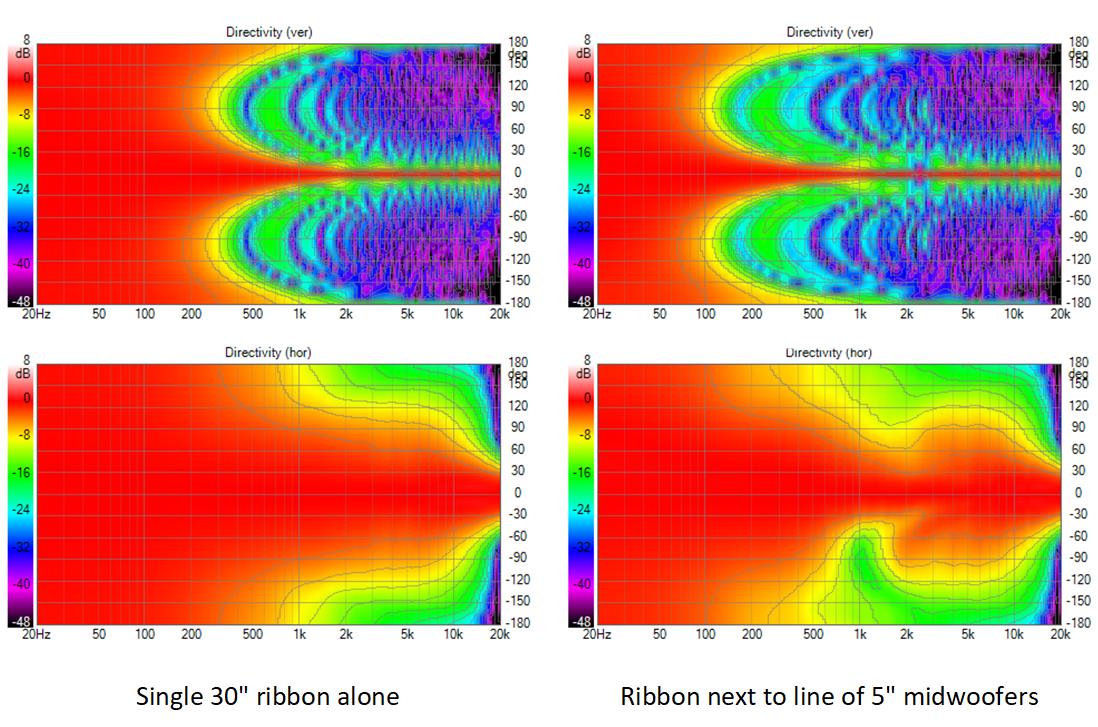
The system sim shows the issue with 2 way side by side arrays - the abrupt narrowing of the polars near XO on one side. I don't think this is problematic if the arrays are in a corner and that dip faces a sidewall with absorber.
Obviously a 30" tall ribbon is going to have a narrow vertical response. 30" may be sufficient for seated only listening but you would want to stack them 2 or 3 tall for a wider response and to ensure that your listening position was in line array nearfield.
I would also point out how wide the response is. If anything its too wide, certainly too wide for a small untreated room.
Attachments

I originally thought I could model a single R45 in the diffraction tool at high resolution by segmenting it into 40-50 small rectangles and then place 2 or 3 of these drivers on my schematic. When I did this, I found an axial dip in the system response. Kimmosto showed me in the Vituix thread that this could be eliminated by tilting the drivers vetically to equalize the path length distance from points along the ribbon to the microphone. It was surprising that a horizontal anomaly could be fixed by a vertical tilt.
It only then occurred to me that the continuous ribbon has a continuous path length difference along its length and will therefore show some of the same response ripple as do the discrete arrays.
Kimmo also acknowledged that this dip was due to some approximations in his directivity calculations. The best way to model the stack of 2 ribbons would be a stack of 50 or more individual drivers with the middle driver muted. But Vituix really bogs down under such a load. Therefore I modelled the double driver in the diffraction tool as 49 individual elements - per Kimmo's advice except the center/gap driver isn't muted. This gives a small simulation inaccuracy as the gap between drivers isn't modelled. However the gap is on the order of 5% of the radiating surface whereas the rule of thumb advises keeping the gap under 10%.
with that as preface
Here are the double and triple ribbon simulated responses
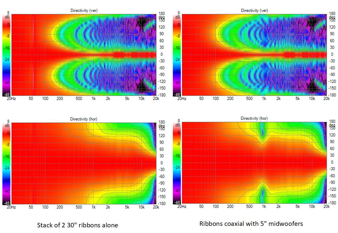
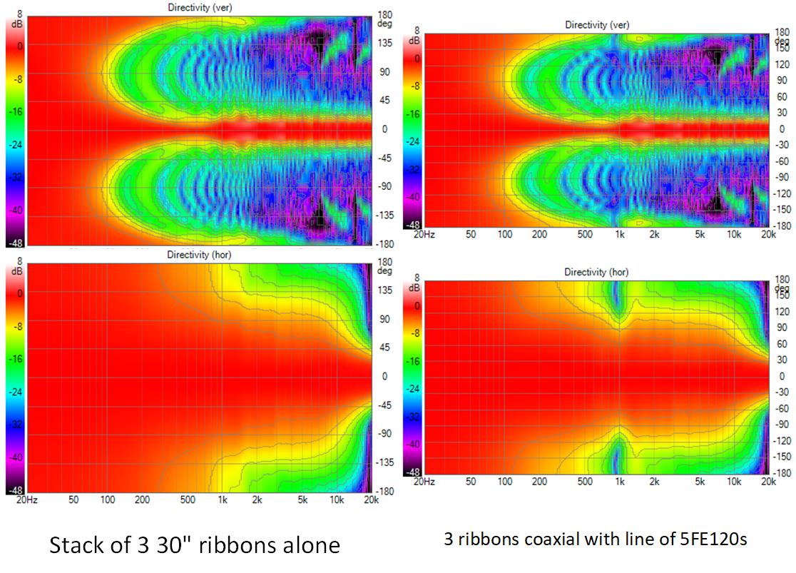
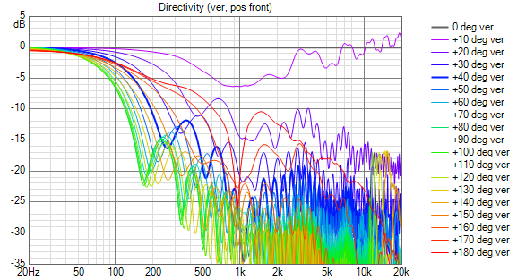
The midwoofer line's response narrows between 500 Hz and 1 Khz. This could probably be fixed with some shading but I have yet to address it. Except for that, the vertical polars look pretty good. But polars can be misleading; here is the vertical line chart for the double R45
and for the triple R45
so the long ribbon is not a panacea but it looks like something that enables a very good solution, but perhaps not the best for a smaller small room given its very wide response.
Attachments


It is pretty easy to make a DIY ribbon tweeter 200 cm long. And the impedance is not that bad either. As I remember it it was about 1,5 Ohms.
I made a lot of these in the ´80 and even a fullrange speaker with five of these side by side. The problem was the powerhandling below 50 hz. They went down there (big baffle) but the movement of the bands were too much.
With todays Neo magnets it would be easy to make one that only needed to reach 1000 hz.
Take a look at the ribbon tweeter for Magnepan MG20 it was made this way.
Two rows of magnets with a about 15-20 mm alu band between. Preferably a alu/plastic foil bond, as the alu then can be very thin and the impedance higher


In 1987 I bought a pair of Carver Amazing Platinum Edition speakers with 60" x 5" ribbon that played down to 200 Hz, each flanked by 4 12" open baffle woofers. It lived up to its name, including dimming the lights on bass peaks because my house then was at the end of 500 feet of quad ought gauge primary wire.
- Home
- Loudspeakers
- Full Range
- Full range line array for wall or corner placement