Here are responses at +500 mm and -250 mm vertical offset.
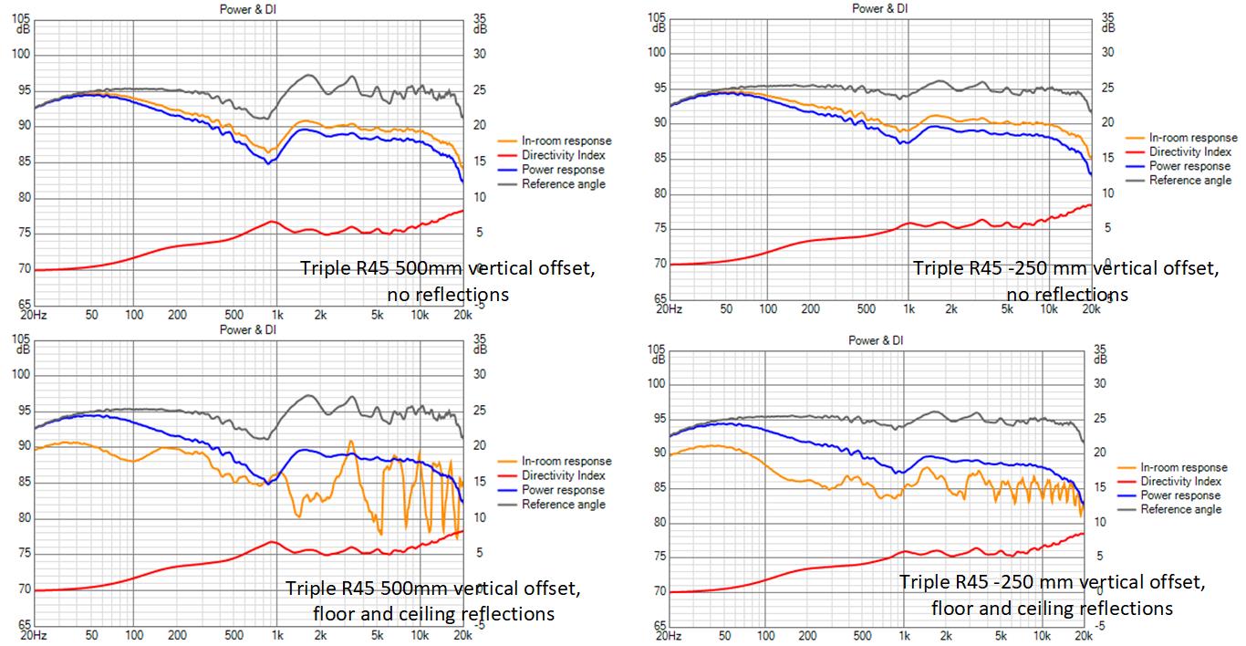
The response with no reflections enabled shows what the vertical microphone shift does to the crossover phase. Surprisingly, the vertical offset affects what intuitively seems a purely horizontal crossover.
The magnitude of the floor and ceiling combing makes one wonder why bother with continuous ribbon if combing is unavoidable. I'm surprised its so high at the 500 mm offset, given how nice the room response is at array center.
Based on these I would still consider R45 2 way for seated only listening, which likely requires only a single 30" ribbon on each side.
Attachments
a word of caution is on order. I'm not nearly as confident in the synthesized directivity for these ribbons so for smaller planars or cone driver. The unequalized triple R45 shows the same/similar FR ripple as do the stacks of full length drivers and that implies that due to Vituix driver limitations I didn't break the tall ribbon up into a sufficient number of pieces. Thus, it might be better vs height than these sims show.
For sure these sims are not representative of continuous ribbons!
I used 42 18mm tall drivers to model the 30" ribbon so its lightly bettern than a tightly packed stack of tweeters.
I had the same 50 driver limit to work within for the double and triple R45 driver models so the driver segment height nearly doubles and triples respectively for those drivers. That is why the unequalized simulation results look very similar to those of the small full range driver arrays.
I apologize for the miss step but still its progress of a sort. I'm hoping @fluid will come up with directivity files I can use from his work with ABEC.
I did run a sim on a membrane 19mm wide by 762mm long when you mentioned the newform ribbons. The results are awful and I don't believe they are particularly useful so I didn't post them before ") But as you asked here they are.
But as you asked here they are.
I think that this is a situation where simulation and reality have moved far away from each other and the result is not representative. I suspect that it is just more apparent the longer the simulated membrane is. A ribbon is clamped at the edges and the entire membrane will not move at the same time, much like a soft dome is harder to simulate than a hard one that behaves like a piston.
I can try to halve the size and add a gap in between to be more representative of reality and see if makes much of a difference.
But as you asked here they are. I think that this is a situation where simulation and reality have moved far away from each other and the result is not representative. I suspect that it is just more apparent the longer the simulated membrane is. A ribbon is clamped at the edges and the entire membrane will not move at the same time, much like a soft dome is harder to simulate than a hard one that behaves like a piston.
I can try to halve the size and add a gap in between to be more representative of reality and see if makes much of a difference.
Attachments
Thanks, Fluid. Except for the loss of treble, they are very nice, very smooth; especially the H pattern.
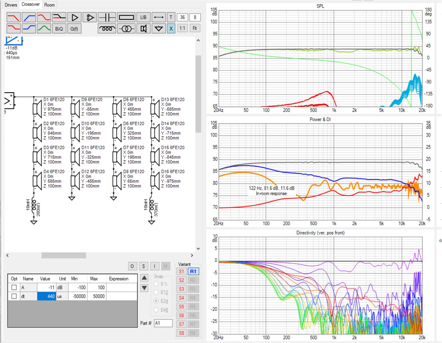
I made a high resolution Vituix model last night and posted it or thought I did. I hope not in the wrong thread but here it is again. The first tries were doing the complete model in the diffraction tool but I realized I could get much higher resolution with a hierarchiccal model. In diffraction tool, I modelled an 18 mm wide by 48 mm tall rectangle, made up of 48 1 mm tall slices. In the XO schematic, 16 of these make up a 30" tall ribbon, 3 sets of 16 model 3 ribbons which I placed with 40 mm gaps between

I made a high resolution Vituix model last night and posted it or thought I did. I hope not in the wrong thread but here it is again. The first tries were doing the complete model in the diffraction tool but I realized I could get much higher resolution with a hierarchiccal model. In diffraction tool, I modelled an 18 mm wide by 48 mm tall rectangle, made up of 48 1 mm tall slices. In the XO schematic, 16 of these make up a 30" tall ribbon, 3 sets of 16 model 3 ribbons which I placed with 40 mm gaps between
Attachments
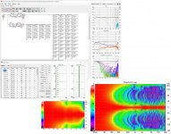
Here is the unequalized triple ribbon raw response and its roll off is not much different than yours which makes me wonder if there was any EQ in the Newform measurement.
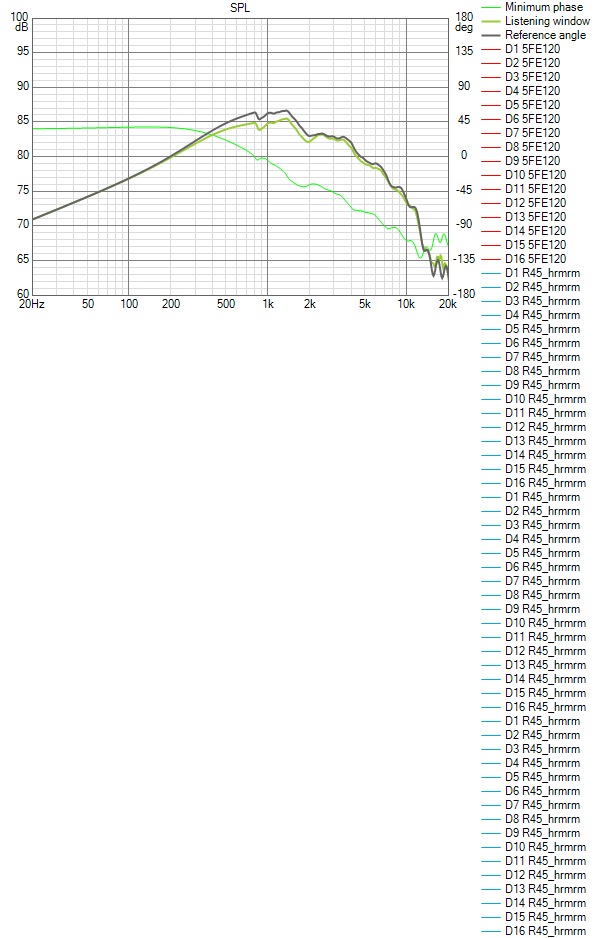
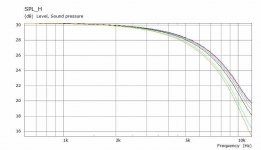
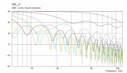
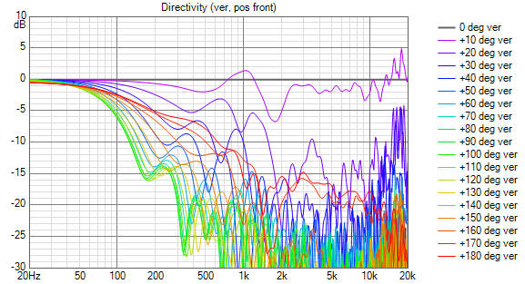
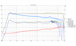
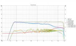
and for completeness, here is a horizontal line chart
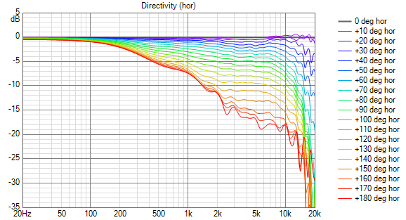
It seems your model is better than you thought. It looks like my model is still not high enough resolution. Frequency response ripple appears above 10 Khz. When I do vertical offsets, the response above 10 Khz changes dramatically
and for completeness, here is a horizontal line chart
It seems your model is better than you thought. It looks like my model is still not high enough resolution. Frequency response ripple appears above 10 Khz. When I do vertical offsets, the response above 10 Khz changes dramatically
Attachments
Looking at them side by side, my model is down 10 db at 10 khz; yours is down 20 khz.
Mine rolls off below 800 Hz where I had no measurement data and Vituix did what it wanted to. Yours is flat down to DC, which would be nice if it matched reality. If that aspect of the sim is suspect, then so is the HF response. If nothing else, I think I would be justified in ignoring the FR ripple in the high end of the Vituix model response
Mine rolls off below 800 Hz where I had no measurement data and Vituix did what it wanted to. Yours is flat down to DC, which would be nice if it matched reality. If that aspect of the sim is suspect, then so is the HF response. If nothing else, I think I would be justified in ignoring the FR ripple in the high end of the Vituix model response
Here is a screenshot showing dramatic effect in treble of just 100 mm vertical offset. I don't believe this sim, certainly not above 10 khz

below 10 khz, I've gotten much better results with shaded full range drivers over limited vertical offsets such as this
below 10 khz, I've gotten much better results with shaded full range drivers over limited vertical offsets such as this
Attachments
I added some shading to the midwoofer line to address the vertical narrowing around XO
This does smooth the 10 degree vertical angle response below XO but the line also has an unexplained narrowing below 2 khz. Nevertheless, I tried raising the XO to 2 khz. The narrowing of vertical response is now confined to 1.5 to 2 khz region
In addition, the room response now shows a dip circa 300 Hz. Equalizing that will be position dependent. The response for small vertical offsets has been improved but not enough for seated through standing range
Attachments

I revised the model to simulate those 3 15" ribbons spaced with 36mm gaps and repositioned the entire set of drivers so the bottom 5FE120 was just touching the floor. This latter step made a significant difference.
Here is room response orange with 100 mm vertical offset green and 200 mm offset light grey.
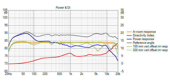
so its good +/- 100 mm from eq ht.
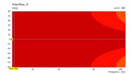
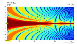
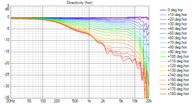
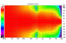
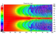
Here are the polars

Moving the bottom end of the array down to ground level accounts for the widening of the vertical polars below XO

Here is room response orange with 100 mm vertical offset green and 200 mm offset light grey.
so its good +/- 100 mm from eq ht.
Here are the polars
Moving the bottom end of the array down to ground level accounts for the widening of the vertical polars below XO
Attachments

An on axis SPL can be added to ABEC as a datafile if you have a response and can attach it as txt I can see if it will change anything. The ABEC model is a perfect membrane which is good for seeing directivity. A lumped Element script and rear volume can be added to simulate the rolloff better. Are there Thiele Small parameters available for it?Looking at them side by side, my model is down 10 db at 10 khz; yours is down 20 khz.
Mine rolls off below 800 Hz where I had no measurement data and Vituix did what it wanted to. Yours is flat down to DC, which would be nice if it matched reality. If that aspect of the sim is suspect, then so is the HF response. If nothing else, I think I would be justified in ignoring the FR ripple in the high end of the Vituix model response
There is no need to model the low end roll off. You can see that all I do is equalize flat then add a high pass. I was just thinking out loud. and no parameters are available (sour grapes )
Its interesting that the perfect membrane has the roll that it does. I wonder what can be done to shape the conductors or the magnetic field or the membrane itself to extend the response...
)Its interesting that the perfect membrane has the roll that it does. I wonder what can be done to shape the conductors or the magnetic field or the membrane itself to extend the response...
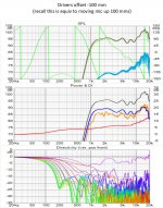
After a struggle, I finally succeeded in getting a model with a single R45 centered at ear height in front of my 5FE120 array. I equalized the direct response and looked at the room response with vertical offsets.
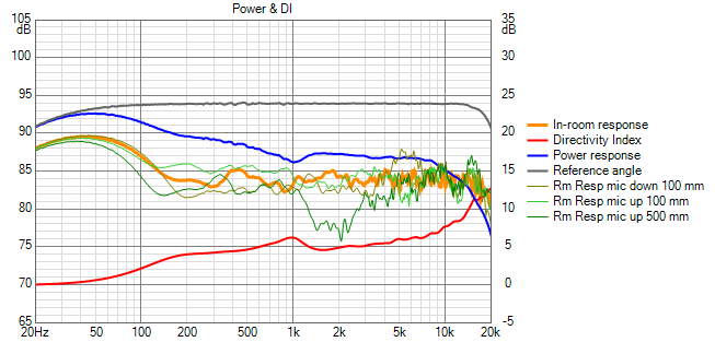
These results are quite promising. At the low end, the responses vs mic height are highly correlated and can be equalized. Most of the rest of the range will be within +/- 2db. The exception is the deeper dip between 1 and 2.5 khz which occurs at near standing height only and could well be a modelling anomaly.
@fluid: getting here has been my distraction for the last couple of days
Attachments

Here's a single TC9, with DSP help to straighten the FR:

Same conditions as the line array plot. It almost makes you wonder about using that (or it's more expensive and efficient sister, the SS 10F) as the tweeter, doesn't it?
Same conditions as the line array plot. It almost makes you wonder about using that (or it's more expensive and efficient sister, the SS 10F) as the tweeter, doesn't it?
Attachments
Last edited:
Those ER and DI graphs sum horizontal and vertical directivity, right?
The peculiar thing about arrays is the huge difference between hor and vert directivity and responseses, as seen in many previous posts.
Anyway, when we put a loudspeaker in a normal listening room, every type of ("normal"/dipole/line array/synergy horn) will have unique sound, and it's personal preference how one qualifies those!
I find line array vertical directivity puzzling. A floor to ceiling line array shouldn't have any in the near field where we listen. If you look for floor and ceiling boundary nulls, you won't find any so perhaps from that point of view it doesn't. But if you measure FR over a range of heights, you will definitely see differences but ones hard to evaluate on a polar map. The most revealing presentation of vertical directivity in Vituix is the vertical line chart, but even with that we still need to do multiple simulations over a range of mic heights to know if the response meets requirements.
Instead of a line chart with lines at stepped angles, a line array for home use should have a line chart with lines at stepped heights. I wonder if Kimmo would agree to calculate it for us.
Does personal preference come into line array vs other architectures? In a way yes, but not what you said. Directivity tells you about the potential size of the sweet spot and where the room may need treatment and you surely will have a preference about those. after that will well engineered and voice speakers of different types each well integrated into their room sound better at their sweet spots?
- Home
- Loudspeakers
- Full Range
- Full range line array for wall or corner placement