Could you try the Allison arrangement of crossing the TC9's above the notch frequency so only the woofer is contributing and being on the floor would not give a bounce in the same way?
I have tried that and the result wasn't worth showing. I will repeat it (later) and remind myself why. I think there is simply not enough room to work with.
If I don't cross over the wg by 600 Hz, vertical pattern control is lost. That means the TC9s would only get to contribute from say 400 Hz up, not even an octave. And then the null moves upwards with vertical offset...
well, that wasn't the explanation.
allowing the woofer to overlap the TC9s removed/moderated the ground bounce null but produced a narrowing of the vertical polars in that region. since then, I've bee trying to moderate the nulls without narrowing the polars. The narrow polars might be the best tradeoff in retrospect
allowing the woofer to overlap the TC9s removed/moderated the ground bounce null but produced a narrowing of the vertical polars in that region. since then, I've bee trying to moderate the nulls without narrowing the polars. The narrow polars might be the best tradeoff in retrospect
Attachments

Yes, its definitely the best!
I neglected to flatten the room response before simulating. The bass is amazingly well correlated. The worst is around the 600 Hz XO between CD and TC9s and really bad there just up around standing ear height at the 3m listening distance
I neglected to flatten the room response before simulating. The bass is amazingly well correlated. The worst is around the 600 Hz XO between CD and TC9s and really bad there just up around standing ear height at the 3m listening distance
Attachments
I have tried that and the result wasn't worth showing....
If I don't cross over the wg by 600 Hz, vertical pattern control is lost. That means the TC9s would only get to contribute from say 400 Hz up, not even an octave. And then the null moves upwards with vertical offset...
You've lost me now as to what works and doesn't and whywell, that wasn't the explanation.
")
Something interesting I came across today here Patent Review: Loudspeaker With a Wave Guide | audioXpress
To extend vertical directivity, as disclosed in the patent (and the Genelec datasheet), the Genelec system adds an oval 215-mm by 100-mm woofer at each of the top and bottom ends of the enclosure, with the output of each of those woofers exiting out of a small (approximately 13 mm) slot running the width of the cabinet. This provides an additional pair of acoustic output sources at each end of the enclosure with a center-to-center separation of approximately 432 mm (17”). The woofers come in and extend down in frequency from 500 Hz to the lower limit of the system (claimed –6 dB at 32 Hz).
This reviewer has found that when working to develop constant directivity systems extending below that of the 1-wavelength limit of a waveguide or transducer dimension, one can deploy hybrid, transitional configurations incorporating a ring-slot source (0.786-wavelength) concentrically surrounding the outer dimension of a driver or waveguide, to maintain constant directivity in both the horizontal and vertical (and oblique) planes, and optionally transition to constant directivity to an even lower frequency application of a spaced, dual acoustic, or rectangular slot or properly oriented quad point sources.
I can see an application for a similar arrangement in a flat baffle or a rolled over waveguide
I think its more about concentricity than about the slit. The slit mostly saves space on the baffle. The concentricity, especially the way I've been doing it, makes the distance from each driver in the array to points along the waveguide axis the same. I've promoted bandpass/slot loaded in the past to reduce CTC, mostly to deaf ears.
I think going to slots on my clock face baffles would definitely improve aesthetics, make for an incremental reduction in CTC, but I would have less confidence in Vituix's abilty to model. Vituix can model a high aspect ratio rectangular diaphragm which could be rotated to tangency to the waveguide rim at each driver location. Vituix accuracy won't be an issue to the extent that radiation from the slits is omnidirectional. It certainly will be at right angles to the slit, so perhaps I should try it.
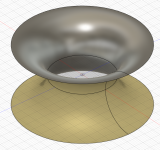
I like the idea incorporating slits/slots in the rollback of a freestanding waveguide. You would want them far enough out on the rollback so little energy would diffract around and down into the waveguide but not so far as to cause a shadow on axis. The slits can be narrower than on the Genelec if limited to passing to 200 Hz as in my latest or even 100Hz. A system with a free standing roll back edge woofers incorporating midwoofers using a woofer for a stand, with extended pattern control compared to a synergy could be quite attractive.
I think going to slots on my clock face baffles would definitely improve aesthetics, make for an incremental reduction in CTC, but I would have less confidence in Vituix's abilty to model. Vituix can model a high aspect ratio rectangular diaphragm which could be rotated to tangency to the waveguide rim at each driver location. Vituix accuracy won't be an issue to the extent that radiation from the slits is omnidirectional. It certainly will be at right angles to the slit, so perhaps I should try it.
I like the idea incorporating slits/slots in the rollback of a freestanding waveguide. You would want them far enough out on the rollback so little energy would diffract around and down into the waveguide but not so far as to cause a shadow on axis. The slits can be narrower than on the Genelec if limited to passing to 200 Hz as in my latest or even 100Hz. A system with a free standing roll back edge woofers incorporating midwoofers using a woofer for a stand, with extended pattern control compared to a synergy could be quite attractive.
Re' my explanation
It was simply wrong; applied to some other idea I had discarded. As soon as I looked at the simulation and saw the narrowing of the vertical polars in the low mid range, I realized that I had discarded the idea on that basis alone and hadn't looked any deeper.
It was simply wrong; applied to some other idea I had discarded. As soon as I looked at the simulation and saw the narrowing of the vertical polars in the low mid range, I realized that I had discarded the idea on that basis alone and hadn't looked any deeper.
In this instance I think it is more about the placement possibilities to use bigger drivers and then tailor the directivity rather than CTC reduction although that is an obvious benefit.I've promoted bandpass/slot loaded in the past to reduce CTC, mostly to deaf ears.
You read my mindA system with a free standing roll back edge woofers incorporating midwoofers using a woofer for a stand, with extended pattern control compared to a synergy could be quite attractive.
I strongly suspect that ports in the waveguide surface of a really good guide will have a more detrimental effect than they do on a conical.
I strongly suspect that ports in the waveguide surface of a really good guide will have a more detrimental effect than they do on a conical.
I think people make too much of that possibility. It has been apparent to all that have not been dissuaded by it that the benefits of Synergy outweigh this one possible detriment. I am amazed by the size of the woofer taps Danley gets away with. For my one Synergy I used very small midrange taps and no woofer taps. If there was an effect from the taps, there was so much else going on in the room I couldn't see it.
Doing this, you avoid the issue and get better in room response for the same size waveguide so its a clear win.
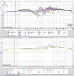
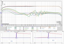
I wondered what this rim slot extended waveguide simulation compared to my coarse frequency shaded line array. Top group is the waveguide, bottom group is the line array
This just goes to show how hard it is to beat the line array for vertical directivity control. To be fair to the waveguide, with it I am able to include wall reflections in the simulation with only 2 db absorption. I disable wall reflections completely for the line array; it clearly needs treatment at first reflection points. My use is in a corner with pads on both adjacent walls.
This just goes to show how hard it is to beat the line array for vertical directivity control. To be fair to the waveguide, with it I am able to include wall reflections in the simulation with only 2 db absorption. I disable wall reflections completely for the line array; it clearly needs treatment at first reflection points. My use is in a corner with pads on both adjacent walls.
Attachments

I strongly suspect that ports in the waveguide surface of a really good guide will have a more detrimental effect than they do on a conical.
Could those ports not be modeled effectively, to find a good compromise?
Some air flow control, embedded in the model around the ports to minimize their disruptive nature? I remember the ATH tread, where the JBL M2 knuckles were one of the features, not that we need those, but we may be able to steer the properties, much like that sloth from Genelec.
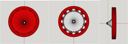
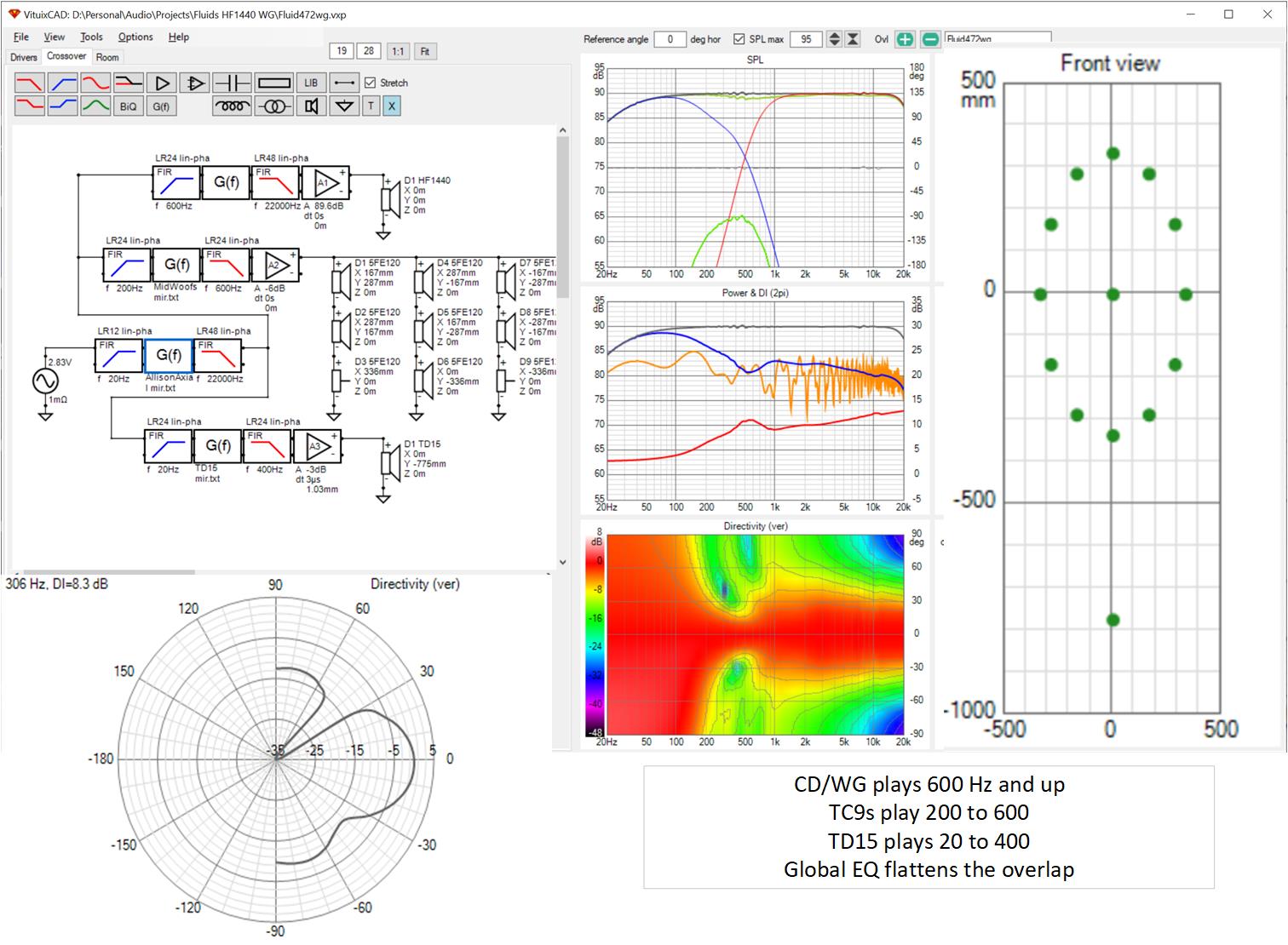
I took a stab at modelling the slot mids in Vituix. Since they are being used in a frequency range where the directivity is determined by mouth dimensions, I modelled the slot as a 10mm wide by 58 mm tall rectangle and placed 12 of them on the baffle touching the rim of the waveguide and rotating each for tangency. HornResp was "OK" with this slot area even modelling and OK with only 1L per TC9 back chamber given 200 Hz XO.
The slots reduced wg-mid CTC allowing me to raise XO to 800 Hz. The mids take over from the wg at a higher frequency where it has better pattern control but don't extend the pattern control lower as did the full exposed cone mids.
But I still had pesky floor response dip circa 300 Hz. Said dip can be filled with EQ and the EQ holds fairly well for +-200mm seated height variation but I wanted to do better.
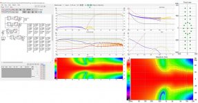
I tried line array bass with double lines (to maintain H control) of 5" midwoofers above and below the clock face. XO to them is at 400 Hz. They overlap the TC9 slots that play 200 to 800 Hz. This seems to have done the trick!

The faint green line in the top graph is the listening window average response for a +- 30 degree window. It shows that the narrowing in the midbass of the vertical window isn't problematic.
You can see driver placement on the baffle in the far right of the composite screenshot.
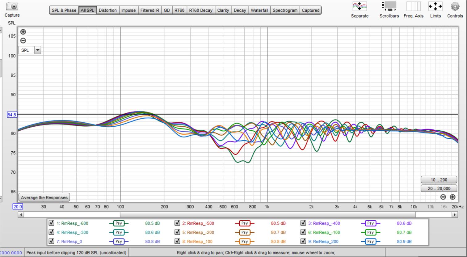
Here are the room responses for a tight in corner location without absorbers on the wall.
The 300 Hz dip is completely gone. There is more variation than I would like in the 500 Hz to 2 khz region. This is entirely doe to reflections; simulated anechoically the response is as clean as the waveguide's abec simulated response. The XO between wg and TC9s even holds over vertical offsets.
pay no attention)) to the 3db hump circa 2 khz. I forgot to smooth the room response in REW before using it as an equalization reference in Vituix
The slots reduced wg-mid CTC allowing me to raise XO to 800 Hz. The mids take over from the wg at a higher frequency where it has better pattern control but don't extend the pattern control lower as did the full exposed cone mids.
But I still had pesky floor response dip circa 300 Hz. Said dip can be filled with EQ and the EQ holds fairly well for +-200mm seated height variation but I wanted to do better.
I tried line array bass with double lines (to maintain H control) of 5" midwoofers above and below the clock face. XO to them is at 400 Hz. They overlap the TC9 slots that play 200 to 800 Hz. This seems to have done the trick!
The faint green line in the top graph is the listening window average response for a +- 30 degree window. It shows that the narrowing in the midbass of the vertical window isn't problematic.
You can see driver placement on the baffle in the far right of the composite screenshot.
Here are the room responses for a tight in corner location without absorbers on the wall.
The 300 Hz dip is completely gone. There is more variation than I would like in the 500 Hz to 2 khz region. This is entirely doe to reflections; simulated anechoically the response is as clean as the waveguide's abec simulated response. The XO between wg and TC9s even holds over vertical offsets.
pay no attention
)) to the 3db hump circa 2 khz. I forgot to smooth the room response in REW before using it as an equalization reference in VituixAttachments
Responses vs listening distance
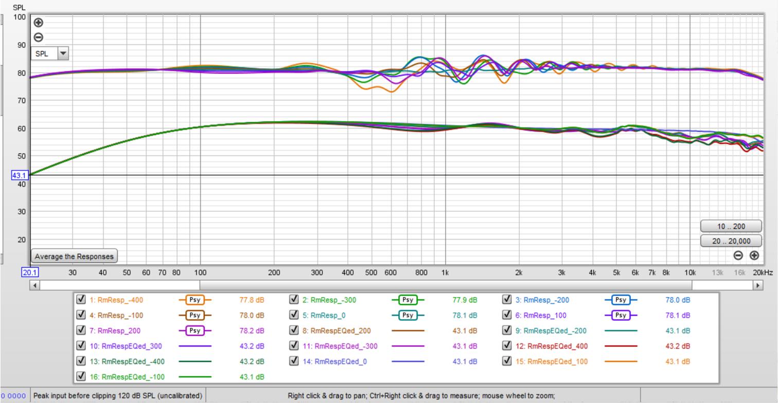
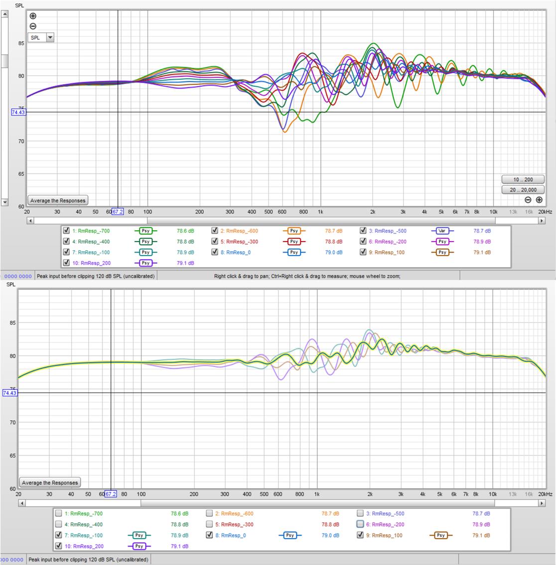
Since this has array bass and monopole top end, let's look at response vs listening distance:
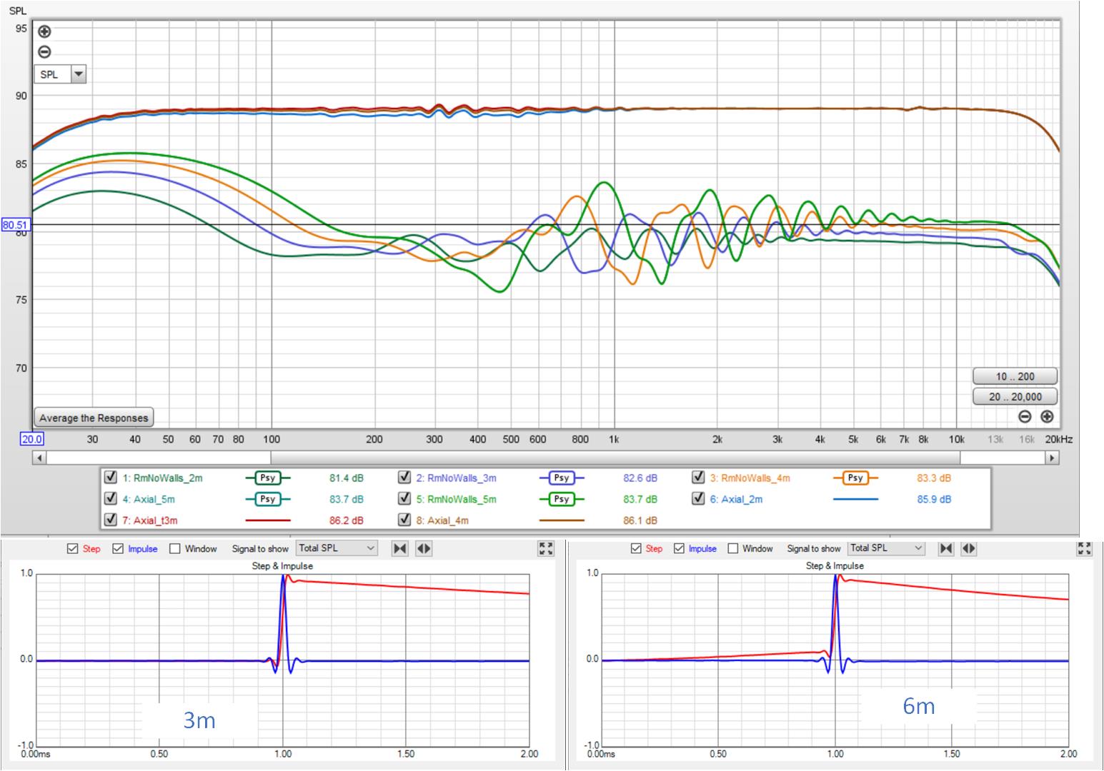
top group are the direct beams; bottom group includes the smoothed room responses, 2m-5m listening distance. No wall reflections included, just floor and ceiling
Since this has array bass and monopole top end, let's look at response vs listening distance:
top group are the direct beams; bottom group includes the smoothed room responses, 2m-5m listening distance. No wall reflections included, just floor and ceiling
Attachments
what are you not seeing? I surrounded fluid's waveguides with a circle of TC9s playing through slots playing 200 through 800 Hz, then overlapped this with a double line array of 5" midwoofers interrupted by the waveguide. It seems wonderfully good except for the amount of FR ripple in 500 Hz to 2 kHz due to mostly floor reflection. It may not be practical given the number of drivers but it sure solves the CTC problem for a waveguide, extends the directivity of the waveguide, and provides quite smooth response up through the midbass; the only "wrinkles" being just above that. Those wrinkles are within +/- 3db for +/- 200mm around equalization height but its concerning that they survive psychoacoustic smoothing.
Last edited:
what are you not seeing? I surrounded fluid's waveguides with a circle of TC9s playing through slots playing 200 through 800 Hz, then overlapped this with a double line array of 5" midwoofers interrupted by the waveguide. It seems wonderfully good except for the amount of FR ripple in 500 Hz to 2 kHz due to mostly floor reflection. It may not be practical given the number of drivers but it sure solves the CTC problem for a waveguide, extends the directivity of the waveguide, and provides quite smooth response up through the midbass; the only "wrinkles" being just above that. Those wrinkles are within +/- 3db for +/- 200mm around equalization height but its concerning that they survive psychoacoustic smoothing.
I did get the text, I guess I'm missing the visualization
.While I'm reading your posts, I'm just in deep thought how to make that array more seamless from top to bottom. There must be a way to get it to behave even better. But at 500 to 2 KHz, it isn't an array.
Could a vertical extension of the midranges (the TC drivers) help to counter that? You've got a circle of them right now. What if you covered more ground at top and bottom in the middle section (even more drivers) to steer the beam there.
Yes they could, and modelling them as separate bandpass enclosures to a flat baffle is easy. Make the port profiles is easy. What I cannot do yet is to find a way to cut the waveguide with it and smooth the junction. Because the profile of the waveguide changes all the way round there is either gaps or ridges that are hard to get rid of. T-Splines could probably be good but they are hard to force to specific geometry. I can project the curve of the port onto the face of the waveguide along a vector and it should be possible to create the inner port as a circle and use guide rails between the two to sweep cut but then the profile changes due to the projection onto the face and it all falls apart. Quite frustrating. I think slots on the edge might be easier.Could those ports not be modeled effectively, to find a good compromise?
Attachments
- Home
- Loudspeakers
- Full Range
- Full range line array for wall or corner placement