What you see in these graphs is not what I see. I have tried my best to explain it, I don't really know what else to say.re' semantics: I sometimes have trouble understanding what you are getting at.
It took a fair number of ATH iterations but I did get an 80 degree beamwidth waveguide that isn't terrible.
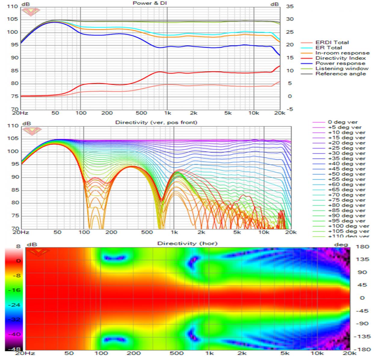
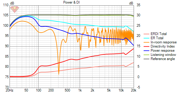
The 1 khz power/DI ripple is reduced.
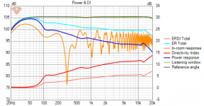
Its interesting to plot its power response and DI on same axes with JBL M2 (red) and Revel Salon (bright light blue):
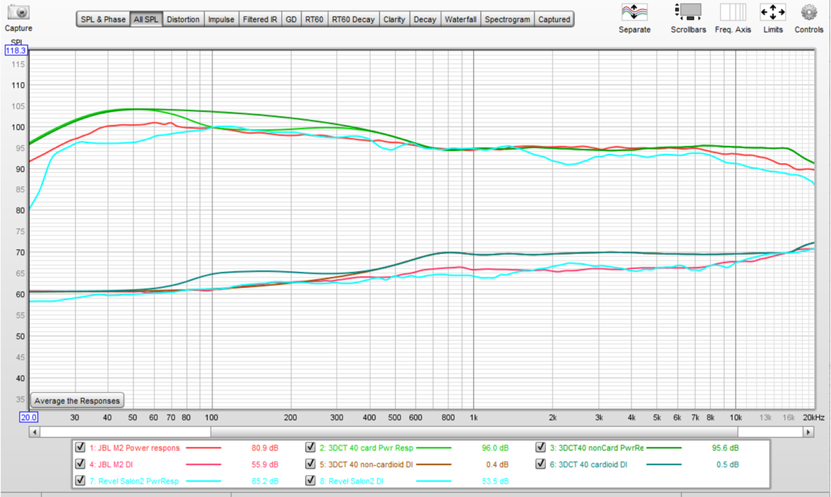
Its surprising to me that Revel was preferred as its measured response is more ragged. It seems to have about the same DI as the M2 but I may have its plot offset, there were no DI ordinate values on the Salon graph that I traced.
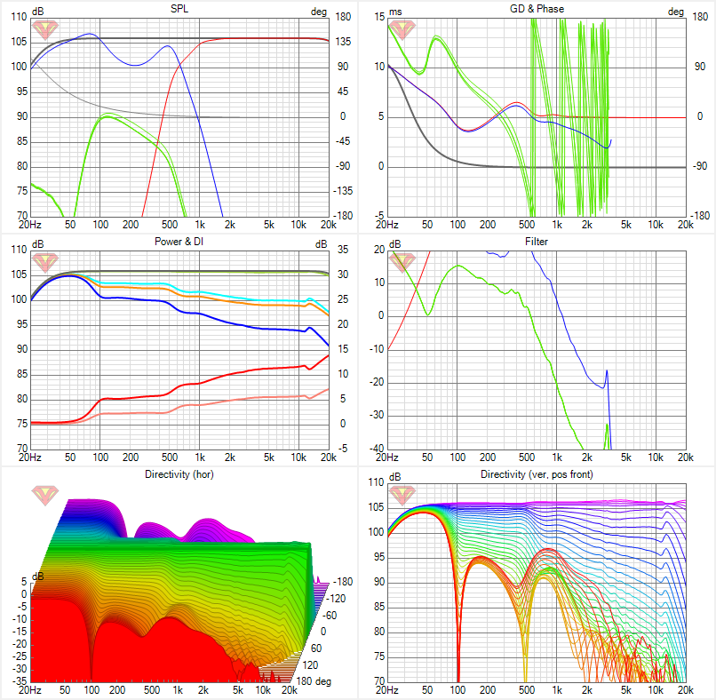
For my design I plotted with both side woofers on and off. Response is identical above 700 Hz. Like M2, power response and DI are flat from 700 Hz up to the very top where narrowing occurs, at higher frequency for the ATH waveguide.
I will keep trying to get a good wide beam waveguide; its proven harder to do than for the 60 degree WG. If these two speakers were not judged harshly for lack of vertical directivity, I shouldn't worry about it either.
The 1 khz power/DI ripple is reduced.
Its interesting to plot its power response and DI on same axes with JBL M2 (red) and Revel Salon (bright light blue):
Its surprising to me that Revel was preferred as its measured response is more ragged. It seems to have about the same DI as the M2 but I may have its plot offset, there were no DI ordinate values on the Salon graph that I traced.
For my design I plotted with both side woofers on and off. Response is identical above 700 Hz. Like M2, power response and DI are flat from 700 Hz up to the very top where narrowing occurs, at higher frequency for the ATH waveguide.
I will keep trying to get a good wide beam waveguide; its proven harder to do than for the 60 degree WG. If these two speakers were not judged harshly for lack of vertical directivity, I shouldn't worry about it either.
Attachments
I'm not saying that there is anything bad about it but the shape and level of the DI curve are making it harder to integrate with the rest of the drivers.
My thinking is the DI should either be as flat as possible as low as possible or it should gently rise from the bottom to the top and any changes should be as smooth as possible.
Your waveguide is already narrow early on so the top end rise doesn't happen till later but if you compare the DI's they are becoming equivalent in the 15 to 18K range.
With Ath when trying to get the response smoother across all angles the DI tends to rise. The same thing happens with bmc0's generator script. If you target a flat DI there seems to always be some ripple in the on axis. Smoothing it out creates a rising DI. I can't shake the feeling that smooth everywhere has got to be better but Earl says the flat DI is more important.
I agree with all that but when I come to grips with what is or seems to be possible I'm lacking in background to make the right tradeoff without benefit of listening. In the meantime I'm doing lots of simulations and XO tweaks, learning from them, and still finding ways to improve the DI smoothness.
Cardioid response disrupts the goal of smoothly rising DI as it puts steps or steep ramps into the DI as you go into and out of the cardioid region. How detrimental are these steps/ramps? I've limited the cardioid range keeping it wide enough to reduce side wall nulls in the room simulation. Cardioid is a compromise to DI to deal with boundary interference. Cardioid can be turned off if boundaries aren't a problem to get that smooth rise of DI towards my waveguide's high DI.
The narrowness of my waveguide is something many would take issue with. I was gratified to see that Tom Danley is not one of them. He uses the same pattern himself in his forthcoming home Synergies and describes 60 degrees as being appropriate for the typical living room. Others in the same thread lauded the pinpoint imaging of Synergies and still others the spaciousness and envelopment of wider patterns like those of Revel Salon and JBL M2. I appreciated your posts there also. I was surprised that no one brought up use of ambient drivers with highly directive speakers to provide that prized spaciousness and envelopment.
re' flat DI vs smooth
Kimmo suggests making neither axial nor power response perfectly smooth but instead compromising so both are good instead of one great and the other fair. In his optimizer, you can set weights and get a weighted balance. I'm not making those compromises yet; but I agree in principle they should be done, probably best in context of listening tests.
Last edited:
I don't know either. I suspect that cardioid in the lower range still makes some sense and that a DI shelf there would not be a major issue as it is in or close to the room controlled region. I have seen graphs from Genelec's GLM that show reduced SBIR type interference in the 200 to 500 Hz region.
In your design it is difficult to match the high directivity waveguide, rim drivers and cardioid lower end response and I think you have done a pretty good job of blending things that just don't want to be blended")
Without 5 blind studies to quote can lead to being shot by a hail of hardcore objective bullets at ASR
With a good waveguide the on axis or listening window can be flat and the power response smooth too. That is harder to do with cones and domes. It's kind of the same compromise Earl makes with his OS guides that there is an on axis issue but not on the designed listening axis and not in the DI or power response. The trade to get both with the waveguide is rising DI. Which could end up being a good idea as the smoothly increasing directivity makes it much easier to integrate with other drivers.
Trying to find that answer is what prompted me to build a CNC.
In your design it is difficult to match the high directivity waveguide, rim drivers and cardioid lower end response and I think you have done a pretty good job of blending things that just don't want to be blended
Without 5 blind studies to quote can lead to being shot by a hail of hardcore objective bullets at ASR
With a good waveguide the on axis or listening window can be flat and the power response smooth too. That is harder to do with cones and domes. It's kind of the same compromise Earl makes with his OS guides that there is an on axis issue but not on the designed listening axis and not in the DI or power response. The trade to get both with the waveguide is rising DI. Which could end up being a good idea as the smoothly increasing directivity makes it much easier to integrate with other drivers.
Trying to find that answer is what prompted me to build a CNC.
I'm sure your CNC will get a good workout once you get going with it!
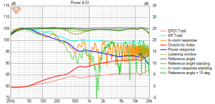
The steps in the power response and DI disappear with a 650 Hz crossover. That's necessitates a change to 1.4" exit CD and waveguide which won't be as good at the very top where I can't hear anyway. I started out with a 1.4" exit, read the discussion on HOMs in the ATH thread, saw issues myself in the ABEC results and moved to 1" throat. I really wanted to make that work but I really can't argue with the results in the lower midrange with the lower XO, now that I have re-examined them.

There are dips in the DI at 473 Hz and 13 kHz. I've split the difference between axial and power response at 473 Hz with a .5db PEQ. This didn't affect the DI though. I'm hoping to refine the waveguide further at the top end but I should point out re' the bump at 7 kHz - its +1 db, -.5db for angles 0,5, 10 and 15 degrees. WG response was normalized at 10 degrees.
The steps in the power response and DI disappear with a 650 Hz crossover. That's necessitates a change to 1.4" exit CD and waveguide which won't be as good at the very top where I can't hear anyway. I started out with a 1.4" exit, read the discussion on HOMs in the ATH thread, saw issues myself in the ABEC results and moved to 1" throat. I really wanted to make that work but I really can't argue with the results in the lower midrange with the lower XO, now that I have re-examined them.
There are dips in the DI at 473 Hz and 13 kHz. I've split the difference between axial and power response at 473 Hz with a .5db PEQ. This didn't affect the DI though. I'm hoping to refine the waveguide further at the top end but I should point out re' the bump at 7 kHz - its +1 db, -.5db for angles 0,5, 10 and 15 degrees. WG response was normalized at 10 degrees.
Attachments
Ha Ha I just couldn't resist.Lol, I didn't want to say anything..
Made box 20 mm x 20 mm bigger so I could simplify interior partions
Non longer using bandpass front and side woofers, still rear mounting though
is response improved - no longer need PEQ at 480 hz but Di slope less constant
can't wait to hear what image waterfall in place of polar map evokes
Non longer using bandpass front and side woofers, still rear mounting though
is response improved - no longer need PEQ at 480 hz but Di slope less constant
can't wait to hear what image waterfall in place of polar map evokes
Attachments

Last edited:
making room for vertical partitions between front and side drivers, instead of horizontal, for an easier ship in a bottle maintenance if its ever necessary to replace a woofer
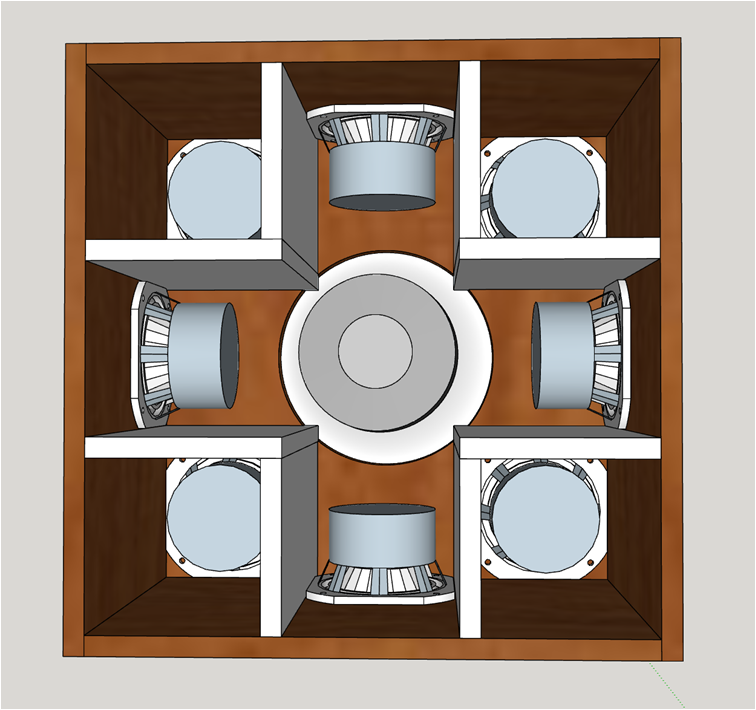
one remaining issue is whether I need to equalize the volume for front and side woofers. I can do that by lowering the height of those vertical partitions and then putting a floor in to seal off the middle lower part of the box containing the side woofers and CD. Then I have to make that interior partition removable as will be the back. But I can equalize both fronts and sides to the same curves despite unequal volumes, just costs more power in the lower volume set so do I need to?
one remaining issue is whether I need to equalize the volume for front and side woofers. I can do that by lowering the height of those vertical partitions and then putting a floor in to seal off the middle lower part of the box containing the side woofers and CD. Then I have to make that interior partition removable as will be the back. But I can equalize both fronts and sides to the same curves despite unequal volumes, just costs more power in the lower volume set so do I need to?
Attachments
Do I have a point source?
Tom Danley says CTC must be less than 1/4 lambda at XO for point source combination of the drivers. The only theoretical basis I can see for this is the geometrical observation that there is no angle from which you can view that combination of drivers from which there will be negative summation. For example, out at +/- 90 degrees the mids arrive at summation point 90 degrees out of phase, contributing nothing but also taking nothing away. This suggests that at the smaller angles as limited by horn walls, you can get point source behavior with a greater CTC. That thinking was in the back of my mind when I started down this path. My simulation results show it to be true. At the current 700 Hz XO, the CTC is .42 lambda.
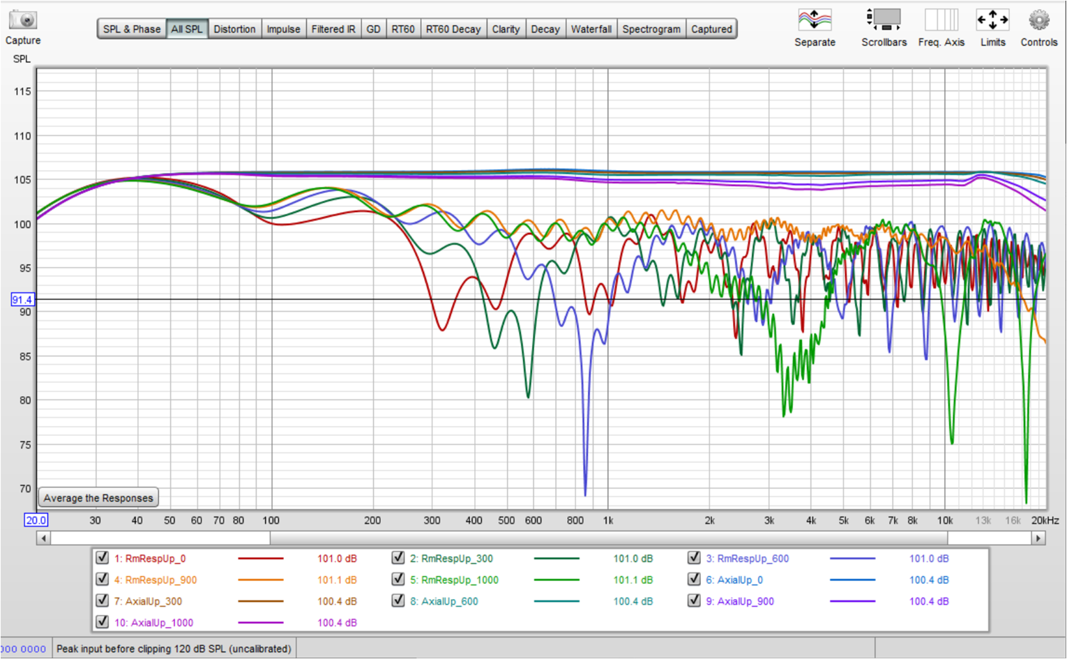
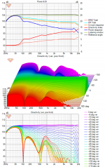
After I made the graph, I noticed that the data had been taken at horizontal reference angle of -30 degrees, after normalization/EQ at 10 degrees. I simulated vertical offsets of 0 and multiples of 300 mm offsets up and down, and also 1m, the furthest Vituix will go
the top set of traces are the axial responses. All you see there is a fall of treble at and near the outer limits of the beam. Nothing happens at the XO; its transparent.
The lower set is the in-room response with all reflections enabled at 2db absorption. The nulls move with position as expected.
Tom Danley says CTC must be less than 1/4 lambda at XO for point source combination of the drivers. The only theoretical basis I can see for this is the geometrical observation that there is no angle from which you can view that combination of drivers from which there will be negative summation. For example, out at +/- 90 degrees the mids arrive at summation point 90 degrees out of phase, contributing nothing but also taking nothing away. This suggests that at the smaller angles as limited by horn walls, you can get point source behavior with a greater CTC. That thinking was in the back of my mind when I started down this path. My simulation results show it to be true. At the current 700 Hz XO, the CTC is .42 lambda.
After I made the graph, I noticed that the data had been taken at horizontal reference angle of -30 degrees, after normalization/EQ at 10 degrees. I simulated vertical offsets of 0 and multiples of 300 mm offsets up and down, and also 1m, the furthest Vituix will go
the top set of traces are the axial responses. All you see there is a fall of treble at and near the outer limits of the beam. Nothing happens at the XO; its transparent.
The lower set is the in-room response with all reflections enabled at 2db absorption. The nulls move with position as expected.
Attachments
Last edited:
The difference between rim drivers or drivers on the baffle near the rim and drivers within a Synergy horn is that the summation occurs at the listening point instead of in the horn itself near the mid ports. There is no point to looking at summation out past the horn pattern angle because there is nothing there from the CD to sum with.

The law of cosines can be used to compute the delta path length for the mids/rim drivers at some offset angle vs on axis, where DSP delay has been used to zero it relative to the CD. When I return from my appt. I will work the numbers.
The law of cosines can be used to compute the delta path length for the mids/rim drivers at some offset angle vs on axis, where DSP delay has been used to zero it relative to the CD. When I return from my appt. I will work the numbers.
Attachments
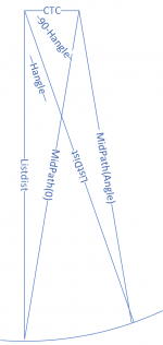
that triangle is an oversimplification. Sketchup can picture the actual case and show the path lengths directly.
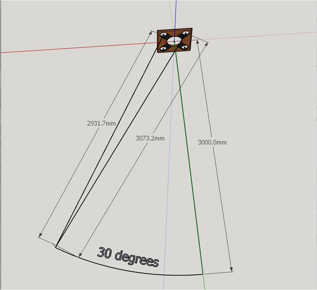
First the delays are adjusted so all drivers are in phase on axis. As the mic is moved off the horizontal axis, the distance to the nearer driver pair decreases by about the same amount as the distance to the further driver pair increases. Contribution from one pair of drivers is leading; the other is lagging in phase. So long as the phase shift remains less than 90 degrees, their contributions to the aggregate will be positive and no nulls will be produced.
from sketchup
Plonaxis 3000
PLoff30short 2931.7
PLoff30long 3073.2
with the help of a simple spreadsheet to do the arithmetic
DeltaPathShort 68.3 mm
DeltaPathLong -73.2 mm
90 degree Freq Short 1259.150805 Hz
90 degree Freq Long -1174.863388 Hz
XO freq 700 Hz
Lambda XO 491.43 mm
Delta phase short at XO 50.03 degrees
Delta phase long at XO -53.62 degrees
According to this, my XO could be quite a bit higher than the 700 Hz I chose for best power response and DI smoothness. Combination with drivers outside the horn is very different than summing inside near the throat. Its more like line array combing in that the delta path length decreases with increasing listening distance. There is plenty of margin in the computed 1174 Hz max XO to allow for use of a waveguide with a wider pattern.
Attachments
The previous post wasn't precisely correct; this one is better. Since delays are adjusted to be equal on axis, the delay compensated delta path lengths are the differences between the on axis and off axis differences for each driver. On axis at 3m, the distance from a corner driver is 3006.7mm for a difference of 6.7mm from the previous post.

If I apply the formula for the sum of two sinusoids of equal frequency and approximately equal but opposite phases, I get sin(jwt) cos(ph), where ph is the average of the magnitudes of the phase shifts. The cosine term is an attenuation; for 90 degrees it would be zero. For ~50 degrees, its about 1.9 db. Bitux has the drop at the 700 Hz XO at 30 degrees reference angle as -2.7 db.
If I apply the formula for the sum of two sinusoids of equal frequency and approximately equal but opposite phases, I get sin(jwt) cos(ph), where ph is the average of the magnitudes of the phase shifts. The cosine term is an attenuation; for 90 degrees it would be zero. For ~50 degrees, its about 1.9 db. Bitux has the drop at the 700 Hz XO at 30 degrees reference angle as -2.7 db.
Attachments
what would be the CTC with a 12" woofer mated with this 300 mm diameter waveguide?
300 mm +/- depending on whether you rear mounted for some overlap or not. Here I would call the CTC 142 mm which is the X,Y offsets to the 4 corners rim drivers, so CTC has been halved.
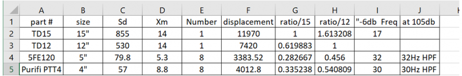
Do those 4 5" drivers augmented by 4 more below 100 Hz have enough displacement for this to be considered a full range speaker and used stand alone?

The answer depends on the room and room gain but the 8 5's are no match for a single AE 12" or 15" woofer so I've expect I will use my 15's in the room below 60 or 80 Hz.
I briefly considered the Purifi PTT4s until I saw the price. At that price, I prefer to brute force with subs and get benefit of multi-subs. That goes against small but two of my 15"s are already serving as end tables.
300 mm +/- depending on whether you rear mounted for some overlap or not. Here I would call the CTC 142 mm which is the X,Y offsets to the 4 corners rim drivers, so CTC has been halved.
Do those 4 5" drivers augmented by 4 more below 100 Hz have enough displacement for this to be considered a full range speaker and used stand alone?
The answer depends on the room and room gain but the 8 5's are no match for a single AE 12" or 15" woofer so I've expect I will use my 15's in the room below 60 or 80 Hz.
I briefly considered the Purifi PTT4s until I saw the price. At that price, I prefer to brute force with subs and get benefit of multi-subs. That goes against small but two of my 15"s are already serving as end tables.
Attachments
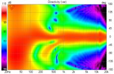
Controlled as the directivity of this 3D Cardioid Top is, it still has a boundary null. This picture includes wall, floor and ceiling reflections for a near the corner position.
What can be done about that null? Despite knowing better I tried cancelling it with a 15" sub placed directly behind the Top.
The cancellation holds quite well over 0+/-15 degree H window and still fairly well at standing height after EQ at seated height

but the effect on vertical polar map is dramatic

I don't know if this is a good idea or not; it needs to be tried. That would be a good way to test the audibility of these kind of nulls.
I'm planning to use ambience speakers. If their response is extended down to 300 Hz, they would certainly fill in the belly of the null, reducing its depth. If the ambience speakers were behind the Tops, the cancellation filter chain could be included in their processing.
What can be done about that null? Despite knowing better I tried cancelling it with a 15" sub placed directly behind the Top.
The cancellation holds quite well over 0+/-15 degree H window and still fairly well at standing height after EQ at seated height
but the effect on vertical polar map is dramatic
I don't know if this is a good idea or not; it needs to be tried. That would be a good way to test the audibility of these kind of nulls.
I'm planning to use ambience speakers. If their response is extended down to 300 Hz, they would certainly fill in the belly of the null, reducing its depth. If the ambience speakers were behind the Tops, the cancellation filter chain could be included in their processing.
Attachments
Did you read The 'Circles of Doom'.....Open baffleless full range speakers.?
Just a heads up.... I sort of expect controlled directivity + Ambience to be able to do something similar...
Just a heads up.... I sort of expect controlled directivity + Ambience to be able to do something similar...
- Home
- Loudspeakers
- Full Range
- Full range line array for wall or corner placement