Hi Priesma I like 2SK1058/2SJ162
Telstar I used these for a friends 2kW amp 13 per rail. Yes there is nothing wrong with them, It is a matter of preference. My own designs are exclusively L-MOSFET, my latest design for ZUS was L-MOSFET BJT Hybrid, and excellent sound. But for myself in my environment I am happy as a pig with four L-MOSFETS parallel per rail.
Telstar I used these for a friends 2kW amp 13 per rail. Yes there is nothing wrong with them, It is a matter of preference. My own designs are exclusively L-MOSFET, my latest design for ZUS was L-MOSFET BJT Hybrid, and excellent sound. But for myself in my environment I am happy as a pig with four L-MOSFETS parallel per rail.
Credit to Alex MM
The boards shown here are a DIRECT result of the Professional, Great and Hard WORK of ALEX MM.
Without his help, guidance and direction they, the boards, would not exist")
Any and ALL Thanks are deferred to him and only him.
Now what your flavor 4 or 5 devices per side... and 6 is only a few clicks away, but we will not go there.
The TMC was added and only needs a helper circuit that OStripper suggested some time ago. Once I find that, I will revise these and etch some boards and begin some real testing.
Suggestions, comments are welcomed and expected.
All I am trying to do is to get something to stick a probe or two on to test.
Again thanks to Alex for his patience with me and all the great work he has shared all around.
The boards shown here are a DIRECT result of the Professional, Great and Hard WORK of ALEX MM.
Without his help, guidance and direction they, the boards, would not exist
Any and ALL Thanks are deferred to him and only him.
Now what your flavor 4 or 5 devices per side...
and 6 is only a few clicks away, but we will not go there.The TMC was added and only needs a helper circuit that OStripper suggested some time ago. Once I find that, I will revise these and etch some boards and begin some real testing.
Suggestions, comments are welcomed and expected.
All I am trying to do is to get something to stick a probe or two on to test.
Again thanks to Alex for his patience with me and all the great work he has shared all around.
Attachments
looks good
but I dont understand why continue with such "oldfashioned" layout
outputs heatspread is not very effective
especially when looking at "standard" sized amp casings
Please amplify ( no pun intended) what you are saying, and direct me to some cases that you would suggest for the project...
Please amplify ( no pun intended) what you are saying
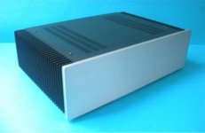
I hope this illustrates what Im trying to say
as you can see I would suggest a kind of reversed layout, having outputs at lower half of heatsink
amp box cases ?
could well be a modushop from Italy
be aware that each heatsink of the bigger 400mm probably consist of two halfs assembled, and might not be optimal
apart from heat spread issues, I could imagine a risk of putting stress on a printboard
well, ok, its a europe product, and might not be an option for you living in US
but still illustrates a good design
Attachments
I hope this illustrates what Im trying to say
as you can see I would suggest a kind of reversed layout, having outputs at lower half of heatsink
amp box cases ?
could well be a modushop from Italy
be aware that each heatsink of the bigger 400mm probably consist of two halfs assembled, and might not be optimal
apart from heat spread issues, I could imagine a risk of putting stress on a printboard
Ok I see what you are saying...
I would think that once we get to that point that design is much better.
This board is JUST for testing of the design topology, it is not intended for group buys etc. and beyond....
I found the post by OS and I am going to add the R/C between the Collectors at the top of the cascade above the input FETS.
This board is JUST for testing of the design topology, it is not intended for group buys etc. and beyond....
ok
but shouldnt it optimally be the same, or close, to save a lot of exstra work
Optimally, I would have liked to have had this board in its unfinished state back in NOV.
I am at this point just HOPEFULLY improving on what Alex put forth 2 months ago.
The choice I made was to go with what is available right now. The SOIC fet LSK389a was not my first choice, its what I hope to get in hand in few days.
All told I am just happy to have SOMETHING to work with, OPTIMAL or not.
BTW no one mentioned Output Transistor Spread when Alex put it up before.
I hope this illustrates what Im trying to say
as you can see I would suggest a kind of reversed layout, having outputs at lower half of heatsink
amp box cases ?
could well be a modushop from Italy
be aware that each heatsink of the bigger 400mm probably consist of two halfs assembled, and might not be optimal
apart from heat spread issues, I could imagine a risk of putting stress on a printboard
well, ok, its a europe product, and might not be an option for you living in US
but still illustrates a good design
HOW much for the cases? How much for shipping to the states?
Anyone know of a like minded case available in the States?
The modu cases look good and reasonably priced. I wonder how their build quality is.
Split heatsinks are a no-go.
I don't believe the OP device arrangement will mater too much. But I should measure it in my amp to verify and tell you the results.
A prototype with another layout than the final product doesn't make much sense.
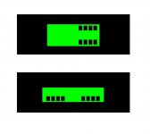
Is there another view available that is higher resolution and not green in green?
Split heatsinks are a no-go.
I don't believe the OP device arrangement will mater too much. But I should measure it in my amp to verify and tell you the results.
A prototype with another layout than the final product doesn't make much sense.
Is there another view available that is higher resolution and not green in green?
The modu cases look good and reasonably priced. I wonder how their build quality is.
Split heatsinks are a no-go.
I don't believe the OP device arrangement will mater too much. But I should measure it in my amp to verify and tell you the results.
A prototype with another layout than the final product doesn't make much sense.
Is there another view available that is higher resolution and not green in green?
Attachments
This "oldfashioned" layout has the advantage of keeping the input stage at one end, far from the transformer and close by the input sockets.
"Old fashioned" is a "wire with gain" .
Works the best of all the layouts , no long inductive paths snaking around the board. Input section sees very little of what the OPS dishes out. Same as mine but for a wider "spread" in the OP devices. Also, NFB takeoff point is ideal - easy to implement separate ground and supplies, as well. Nice !!OS
Should not have to trouble shoot or repair, it should work first time. My layouts follow the same pattern, as OS says short signal and feedback path, OP wont interfere. High current side far from input.
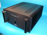
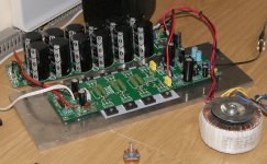
This amp front end driven from 95V series shunt OP is hybrid L-MOS BJT running at 80V. Completed on 5 th Nov 2010, final stages of integration into chassis. Has excellent sound and uses typical layout as Krisfr/OS with zero noise. Also this layout fits nicely on the side plate to which heat sinks extrusion will be bolted from inside.
Don't consider the transformer, it is for testing purposes only, final will have 500VA per channel supported by 60 000 uF per rail per amp.
Kind regards
Nico
Attachments
http://www.diyaudio.com/forums/soli...s-improvements-stability-114.html#post2383189
The added cap and res from this post number 1133 has been added as well as TMC to the board.
All the comments have been noted and appraised, so I am ready to etch a couple of these today, then tin drill and stuff.
Thanks for all the input
The added cap and res from this post number 1133 has been added as well as TMC to the board.
All the comments have been noted and appraised, so I am ready to etch a couple of these today, then tin drill and stuff.
Thanks for all the input
Attachments
Last edited:
Krisfr one other comment, the 100nF caps between drain and source, I prefer to place a 100 nF size 0805 SMD cap below the board, it will fit nicely when soldered directly between the two legs of the MOSFETS, I also use SMD caps directly below the power caps so that the 100 nF and electrolytic basically becomes the same cap at the mounting points. We found this a good option when testing for electromagnetic interference/susceptibility.
Krisfr, if you haven't already made the PCB I would turn both of the bottom two transistors (next to 59mm) around and you can glue the two flat sides together for better thermal tracking. Just a comment
Of the 3 types of "pairs" (input differential , cascode , and current mirrors) , the cascode is least affected by thermal mistracking. I went from 0c -50+C (outside to a hairdryer) asymmetrically heating all 3 sets of "pairs". CM will give 1-2mV offset , cascode pair- .5-1 mV , and of course the input pair will offset 10mV or more with a good blast from the hairdryer. Of course , it is ideal to go "face to face" with all the input stage devices , but sometimes ease of layout takes precedence (elimination of long traces). If I could only choose 1 , the input pair would be the one that would HAVE to be thermally coupled , the hairdryer does not lie.
OS
- Home
- Amplifiers
- Solid State
- Goldmund Mods, Improvements, Stability