Hi ZS,Thanks Daniel for your valuable comment,
I have noticed your interesting and inspiring journey with the dual die exicons,
may I PM you with some specific quaestios I am interested in?
Thanks.
Sure no problems to PM me
- Daniel
I think I designed the protection board to mute the output when the rails fall below +/-35V. That's an arbitrary number to make sure the line to the speakes is open before the supply voltage dips so low as to cause a thump or other misbehavior.Thanx for confirming and advice on adjustments. I'll report back once I have it up and running.
Remember, if you cut the rail voltages in half, the maximum output power will be less by a factor of about 4. I think it is fine to use the DH220C boards for a full ground-up DIY build. However, if you want to build it so you can just use existing lower-voltage transformer and caps, might it be better to spring for the higher-voltage tranny and caps, given all of the other hard work and expense you will be putting in?
Cheers,
Bob
May I ask how many output pairs Hafler used in the DH-500C? Were there three or four pairs of 2SK135's/SJ50's? Or even more?I have run +95 Vdc / -95 Vdc rails successfully with the appropriate capacitor ratings using Rick's DH500C boards. The outputs I used were the Exicon dual die Lateral mosfets though.
- Dan
Remember that I have these
") :
:Best regards!
I have used 3 pairs of 250W dual die Exicons per amplifier channel and also 6 pairs per amplifier channel which I am currently using day to day on about +/-75 Vdc to +/-80 Vdc rails.May I ask how many output pairs Hafler used in the DH-500C? Were there three or four pairs of 2SK135's/SJ50's? Or even more?
Remember that I have these
View attachment 1112650
Best regards!
I ran a test at full power at 20 kHz briefly to confirm the drivers were up to it per a suggestion from Bob.
If you plan to use more mosfets in the output stage the output stage pcb needs to be relatively large and you need to take extra precautions to deal with parasitic oscillations perhaps due to track lengths.
I would highly recommend Bob's input stage, the performance, both measured, and in use is very high. The design is Excellent. There is more information in the DH500C thread.
Hope this helps,
- Daniel.
If anyone is looking for replacement power switches for the DH-120/200/220/etc., I just replaced the original in my DH-220C with one of these:
https://www.amazon.com/gp/product/B00LWJ1VHO/
Works fine and fits in the OEM opening.
https://www.amazon.com/gp/product/B00LWJ1VHO/
Works fine and fits in the OEM opening.
iirc I bought 103-7047-EV from Mouser, for my DH-200, wiring was different
In the process I also built a simple soft-start relay pcb for my DH-200, so that the new switch contacts will survive the surge better.
I have a few pcb's left, if anyone wants one, let me know. I showed it in posting #2,242
I'll probably get around to doing a pcb for the ecap replacement, I have some CDE 20mF/80V snap-ins
Last edited:
For those of us without the technical understanding or expertise, sometimes Amazon just has the one thing a tinkerer is looking for when the parts distributors have long lead times, slightly different specs, or discontinued listings.Why A****n? Aren't there any reputable electronics distributors in your country?
Best regards!
Nice work, @rsavas.
"Has anyone used an Antek toroidal transformer in a DH200? Looking for a reference on which one. Yes, I know there’s a transformer from Musical Concepts but seems there might be an accepted Antek PN out there by now also. Thanks"
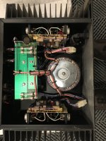
Had these parts around, and thought some photos may help, reading left to right:
1) Smart Theater Systems version of DH220 with toroidal transformer. Similar dimensions as Antek 300VA.
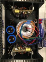
2) AnTek 300VA, in Hafler chassis. AN-3245 seems similar to Theater Systems part. AS 3445 has a shield and dual 15volt windings added
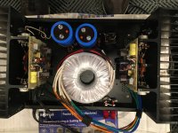
3) AnTek 400VA, in Hafler chassis. AN-4445 and AS-4445 are larger than the Theater Systems part. They both have dual 15volt windings added.
AS has a shield. The larger size should give you slightly more horsepower, but are closer to the high gain area, and more magnetic noise may result from that proximity. The 15 volt windings can be used to provide a cleaner and higher voltage supply to the voltage amp.
I have not tested any of this design speculation, nor have I developed any circuitry for this application.
David
Attachments
All,
I have read the entire 118 page thread. TMI. My brain is 20GB on a good day. 30GB of data in this thread means I had to adopt a FIFO policy.
I’m deep into restoring/modding a DH200 I picked up for almost nothing. After checking DC offset so as not to blow my priceless speakers, and checking bias as found I auditioned it and loved it except for somewhat weak mid-bass. I’ll worry about that later. Most of the consensus suggestions here not involving topology changes are done or on the agenda.
What I have stumbled on now that I can’t recall seeing addressed previously, is the resistors R40-43. PC-6 schematic calls for all four 220 ohm 1/2 watt, R40, 41, 42 and 43. My unit has four 470 ohm. Following the logic discussed here about the changes to PC-19, the PC-19 schematic calls for two 470 ohm on the two 2SK134s, R38 and 39, and two 220 ohm on the two 2SJ49s, R40 and 41. So my unit doesn’t comply with either schematic.
Any ideas what it should be? All 220, all 470, or the odd imbalanced two of each?
Many more questions to come, but this is where I am in the process at the moment.
Thanks to all for this very useful (long) thread.
Jeff
Ok. Thanks Rick. Now I see another anomoly.
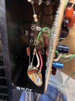
According to the schematic, C18 is supposed to go from drain to chassis on the Q14/15. Does the attached picture not show the cap connected to the gate and since the gates aren’t paralleled, it’s only on Q14?
Also, the 390pf C13 is between gate and source and the consensus is a 33pf should go gate to source instead on N MOSFETs only, correct?
I see at least one or two pictures of these in this thread from other members that also appear to have C18 between gate and chassis! ????
Attachments
- Home
- Amplifiers
- Solid State
- Hafler DH-200/220 Mods