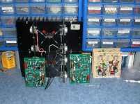
Musical Design sourced parts
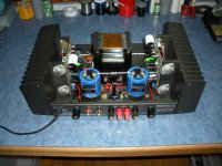
The transformers, are 'plug in replacements' (spec wise) as you can imagine, the amp has a narrow range of what will fit... so 'going bigger' is not an option. 625VA, 50volts, with dual center tapped secondaries, primary can be wired for 240/120. I do not have the current measurements.
The toroid shown, is from, was purchased in the middle 80s, it does not look like the current offerings of Musical Design Transformers
The [Jensen capped] 220 shown in prior post, shows a more 'current' power transformer / parts.
Hello Ozark,
what are the technical datas of the toroids you used in the DH-220 ? voltages, VA and geometrical sizes
BR
Günni
Musical Concepts PA-6
Hope this helps.
If I understand what Gbowling is asking is for is some subjective reviews of the sound of different mods. I have been a fan of John Hillig's work at Musical Concepts since the mid 80's. I have had the PA6 boards installed since they came out. In my opinion this is by far his best design yet. The amp sounds very open and creates a wonderful soundstage. One of the biggest improvements is in the treble response, it is smooth detailed and never etched. I keep a stock Hafler 220 in another system to compare how far the mods have come. The stock Hafler sounds pleasing but flat by comparison. In short the Musical Concepts mods give you an upgrade path as your budget allows and you end up with an amp that will easily compete with amps in $3000 range. It is that good. Hope this helps.
It's great that you guys are making progress on the DH-220C boards, but the question remains...
What are the differences, pros/cons in the DH-220C design and the designs in the musical concepts PA-6 boards, the Qua-Co PA-1 boards, the updated PC-19C boards.
From reading posts, there seems to be a consensus that the MC PA-6 mods sound better than the original PC-19C. But in my mind it's just a little to pricey for a DIY'er.
There also seems to be a lot of info stating that the cascode design is a better option, but I haven't heard anyone specifically evaluating the PC-1 boards on ebay from Qua-Co. Which is a cascode design and there is good info that Qua-Co used to work for Hafler and has a lot of excellent experience.
Which brings us to the DH-220C design. I know Bob Cordell is an expert, has written an excellent book (and I'm patiently waiting for rev 2!). So that design is going to be solid. But is it an improvement on the MC PA-6 or Qua-Co PC-1? If we can get boards and schematics it has the possibility of being in the right price range so that might be a great option.
I agree with some of the comments above that a partially populated board is hard to sell and probably isn't' a good way to go. Either a raw board with parts lists and schematic or a fully populated board are the only logical options, at least in my mind.
To review the options.
- Upgrade caps and parts on the PC-19C. The price for this varies depending what you replace, but nominally I would put the price of this ~$50. The design is proven and the sound is quite good. If your boards are damaged, you can buy new boards on ebay for a reasonable price.
- PA-6 from MC. The lowest kit price for this is $599 with prices for some upgrades over $2000. Geez, you can buy some really great, brand new, modern amps for less. So this seems to be a non-starter, it's just too expensive (my opinion).
- PC-1 on ebay from Qua-Co. This is actually an interesting deal. On sale right now for $225. This includes two new boards (one for each channel), all the parts to stuff it, instructions and schematics. So if you consider a raw board price in the ~30 range, you have $60 worth of boards. If you consider $60-$70 each for parts on the boards, you have maybe another $140. So that's $200. So the guy isn't making much profit and his price is actually about right. I just haven't heard anything about his design or the sound of an amp with his mods.
So is this design as good as the MC PA-6? Better or equal to the PC-19C? Is the Bob Cordell design superior to all of these?
Maybe I should just update my PC-19 with new parts and build a "honey badger," while listening to tunes pumped out by my Hafler!
gabo
I'm not familiar with the MC PA-6, but if someone will post or send me its schematic I will be happy to describe the differences in circuitry between the two.
An SMT version could be very nice, but I agree with Rick that testing of a partially populated board at the seller's end could be almost impossible. However, from a cost point of view, the through-hole components that need to be added might not be that many, might not be that expensive, and might not cost that much for the maker to install, then test the board. The price would be higher, but the value-added of getting a fully populated and tested board would be quite significant. Driver transistors, Feedback network resistors, signal path capacitors, electrolytic capacitors, bias pot and output network components come to mind as the components that likely would need to be through-hole.
Cheers,
Bob
Hi gabo,
maybe this document helps a little more. It' s Bob's presentation from Burning Amp Festival 2016. I think, it would give you some more information.
For me the Qua-Co Design is unknown from performance. The updates for $500 are slightly overprized. A simple way to go is upgrading your existing boards with new Caps (Panasonic FC FR, Nichicon Muse for bipolar) the resistors with Dale CMF55 and MKP capacitors and MICA capacitors. And finally better wiring.
BR
Günni
The DH220C is also covered in the second edition of my book, due out the end of May.
Cheers,
Bob
A fully completed and tested board would be very nice indeed!
Thinking now about the strange parts that customers can and would install in the unpopulated positions, would likely be much better completed.
I had mentioned the semi-populated boards, mostly smd, in an effort to try and have as much outsourced as possible, and a minimum of effort for anyone taking on any prospective purchase and distribution of boards.
The functional test fixture would be likely more than would be practical for such an effort, but if enough boards were sold, could offset the labor of installing the through-hole parts.
The DH220C is also covered in the second edition of my book, due out the end of May.
Cheers,
Bob
Very much looking forward to picking up a copy Bob!
gabo
The DH220C is also covered in the second edition of my book, due out the end of May.
Cheers,
Bob
Now available for pre-order on Amazon!
Waiting with baited breath Bob.
jack in nj
DH-220C design
I have this DH-220C design complete, using all THT, no smt is required to make it fit in the existing board outline.
Sounds like I have one person interested. I have an offer, how about we trade for some jfets, so I can test it out? We can work out any monitory differences. I can supply one or more tested assemblies.
Was thinking of making a small adapter pwb (SO-8(sot-23-6) <-> 6 lead dip) to use the smt package versions of the jfets since they are cheaper than the metal can TO-72-6.
If anyone wants to review the design, I'd be thankful for that, will start with the schematic. Basically merged Bob's presentation material together in one schematic.
Attachments
Last edited:
Hi Gabo, I have tried some of the various options you listed for the DH200 and DH220s.
I have restuffed factory boards in stock configuration, as well as perform the old Pooge upgrade from back in the 80s.
I have not tried the MC boards, but have used the Qu-aco boards in a pair of mono Haflers I have upgraded over the years.
The Qu-aco boards are by far the easier way to go and make for a clean build, although I don't mind restuffing oem boards and trying different PP caps and other quality components in them.
As for comparison, my mono amps are my current favourite, but do not make for an apples to apples comparison because of the dual power supplies in them.
I can tell you though that the DH200 and DH220s that I have restuffed and upgraded do sound pretty darn good, and I have tested them on multiple systems other than my own, and with others evaluating them as well.
My main setup is a pair of IRS Betas, with the mono Haflers driving the mid-high towers and a vintage Threshold S350e driving the bass towers.
Preamp is a Threshold Fet 10/hl, transport is an Oppo UDP-203, and DAC is a Pacific Valve 6922 tube unit.
The system is very revealing, which really helps when evaluating components/builds.
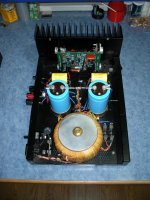
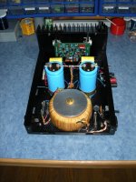
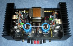
Here are a few photos of some of my past builds.
All of the amps I have built contain various mods, most of which I have learned from this valuable topic, thanks to Fab and other contributors.
I have restuffed factory boards in stock configuration, as well as perform the old Pooge upgrade from back in the 80s.
I have not tried the MC boards, but have used the Qu-aco boards in a pair of mono Haflers I have upgraded over the years.
The Qu-aco boards are by far the easier way to go and make for a clean build, although I don't mind restuffing oem boards and trying different PP caps and other quality components in them.
As for comparison, my mono amps are my current favourite, but do not make for an apples to apples comparison because of the dual power supplies in them.
I can tell you though that the DH200 and DH220s that I have restuffed and upgraded do sound pretty darn good, and I have tested them on multiple systems other than my own, and with others evaluating them as well.
My main setup is a pair of IRS Betas, with the mono Haflers driving the mid-high towers and a vintage Threshold S350e driving the bass towers.
Preamp is a Threshold Fet 10/hl, transport is an Oppo UDP-203, and DAC is a Pacific Valve 6922 tube unit.
The system is very revealing, which really helps when evaluating components/builds.
Here are a few photos of some of my past builds.
All of the amps I have built contain various mods, most of which I have learned from this valuable topic, thanks to Fab and other contributors.
Attachments
Thanks for that msb64, very good info and some impressive amps there.
I have one 220 now and am looking at another one that is for sale. If I wind up with that I will do some more upgrades and bridge them to mono.
Glad to hear you're having great success with the qua-co boards.
gabo
I have one 220 now and am looking at another one that is for sale. If I wind up with that I will do some more upgrades and bridge them to mono.
Glad to hear you're having great success with the qua-co boards.
gabo
Gabo, I should point out what I did for mono amps is not what is typically done with Haflers.
With the DH200 and DH220s you could add a bridging circuit to turn the stereo amp into a mono one.
The benefits of that is much more power, but it also limits the impedance load that you can put on it.
Many Infinity systems can drop far below 4 ohms, which is a no-no for most bridged stereo amps.
I essentially took 2 complete amps/chassis but only used 1 driver board per chassis, insuring that each driver board had its own power supply, with power to spare")
Not only are the Qua-co boards clean, compact and easy to install, the designer Ed Fantasia has been very nice to deal with, and helpful as well.
I still have a stock DH200 and DH220 on hand, as well as at least another DH200 or 2 in parts on hand, so maybe someday I will give the MC boards a try.
At this point though, I have more equipment that I can use in a small house
With the DH200 and DH220s you could add a bridging circuit to turn the stereo amp into a mono one.
The benefits of that is much more power, but it also limits the impedance load that you can put on it.
Many Infinity systems can drop far below 4 ohms, which is a no-no for most bridged stereo amps.
I essentially took 2 complete amps/chassis but only used 1 driver board per chassis, insuring that each driver board had its own power supply, with power to spare
Not only are the Qua-co boards clean, compact and easy to install, the designer Ed Fantasia has been very nice to deal with, and helpful as well.
I still have a stock DH200 and DH220 on hand, as well as at least another DH200 or 2 in parts on hand, so maybe someday I will give the MC boards a try.
At this point though, I have more equipment that I can use in a small house
nice series of amps...
Hey msb64, very nice assemblage of your amp work. KUDOS! nice work.
For me building in multiples, allows for direct comparison of many different ideas... making the path of progress very clear, in terms of hierarchy of importance, where to spend the money and time... allocating resources.
Hi Gabo, I have tried some of the various options you listed for the DH200 and DH220s.
I have restuffed factory boards in stock configuration, as well as perform the old Pooge upgrade from back in the 80s.
I have not tried the MC boards, but have used the Qu-aco boards in a pair of mono Haflers I have upgraded over the years.
The Qu-aco boards are by far the easier way to go and make for a clean build, although I don't mind restuffing oem boards and trying different PP caps and other quality components in them.
As for comparison, my mono amps are my current favourite, but do not make for an apples to apples comparison because of the dual power supplies in them.
I can tell you though that the DH200 and DH220s that I have restuffed and upgraded do sound pretty darn good, and I have tested them on multiple systems other than my own, and with others evaluating them as well.
My main setup is a pair of IRS Betas, with the mono Haflers driving the mid-high towers and a vintage Threshold S350e driving the bass towers.
Preamp is a Threshold Fet 10/hl, transport is an Oppo UDP-203, and DAC is a Pacific Valve 6922 tube unit.
The system is very revealing, which really helps when evaluating components/builds.
Here are a few photos of some of my past builds.
All of the amps I have built contain various mods, most of which I have learned from this valuable topic, thanks to Fab and other contributors.
Hey msb64, very nice assemblage of your amp work. KUDOS! nice work.
For me building in multiples, allows for direct comparison of many different ideas... making the path of progress very clear, in terms of hierarchy of importance, where to spend the money and time... allocating resources.
I have this DH-220C design complete, using all THT, no smt is required to make it fit in the existing board outline.
Sounds like I have one person interested. I have an offer, how about we trade for some jfets, so I can test it out? We can work out any monitory differences. I can supply one or more tested assemblies.
Was thinking of making a small adapter pwb (SO-8(sot-23-6) <-> 6 lead dip) to use the smt package versions of the jfets since they are cheaper than the metal can TO-72-6.
If anyone wants to review the design, I'd be thankful for that, will start with the schematic. Basically merged Bob's presentation material together in one schematic.
hi rsavas,
a few remarks at your schematics:
- what is the use of D3, D4?
- what is the use of R54,C27 at the N-Mosfet sources?
- do you plan to use gate stoppers for the Mosfets?
- do plan to use Source resistors (0R22/5W) for the Mosfets?
Maybe its helpful to add also the external components to the schematics.
BR
Günni
Hi Gunni,
Thanks for your feedback
1) D3,4 are for over voltage input protection, optional
2) I drew the circuit as Hafler had done, R54,C27 are placed across the fuse and close the feedback loop in the event of a speaker fuse failure. Optional as well, only use if you use the speaker fuse as original.
3) gate stoppers will be as was done originally, placed right at the gates.
4) no source resistors are on the pcb, as was done in the original design, if you want them, they will have to be placed at the device leads off the T0-3 device sockets.
5) The schematic represents only what is used on the pcb, External wiring, devices would have to be done on a another separate drawing.
Regards
Rick
Last edited:
Hi Rick,
thanks for the detailed response. Sounds all logical for me.
i am really appriciated about you solution. I will continue with my DH-120C (Cordell version of the PC-25 for the DH-120) and my Hafler 220 version with the2x2SK1058 and 2x2SJ162. that means all is integrated in single PCB with SMD devices, where possible.
Lots of success snd BR
Günni
Hi Ozark HiFi Doctor,
I'm not trying to start a war here, but I have direct experience with both the stock Hafler amplifiers and preamps, and also the versions designed by John Hillig. In every case, the original Hafler circuit is superior. The preamp designs are quite frankly completely botched, and are actually Hafler circuits with the buffer stage removed! The parts weren't even matched closely enough. The same issues go for the power amplifier designs.
It took a bit of work, but I was able to make the preamp stable and sound better. I had to increase some transistor case sizes to lower their case temperature as well as lower the standing current. The dual power supply option was just plain stupid, and improvements to the regulators allowed a single outboard supply to be used.
The Musical Concepts amplifiers mounted the main filter capacitors upside down using the terminals for support! In addition, I had to make some small circuit changes and completely rework the grounds to make them listenable.
My honest appraisal would be to avoid these "upgrades" like the plague. You can do better by properly servicing those original boards, and by matching the transistors. Its the matched diff pairs that make a Hafler (and most any other amplifier) perform at the high levels of performance you are after. There is no need to greatly increase the supply capacitance. Stick with capacitors that fit in the original clamps. Use original sized capacitors on the PCB, higher voltages will give you a better quality capacitor. I can't stress enough how far matching all the transistors will bring you.
Hi Rick,
I'd love to see your work sometime. I don't have a hafler 200 or 220 in here at the moment, but if it is the same schematic you should have a winner there. Did you use any of the smt matched input pairs that are available? That would boost performance. I can match smt transistors, but it is a giant pain in the rear end to do.
Hi msb64,
I don't recommend bridging amplifiers, and the Haflers are included in that statement. You will cut your damping factor in half right off the bat. If you want a real positive boost in performance, go with an electronic crossover and run each drive off it's own amplifier. You will gain in efficiency right away, and the drivers then enjoy full damping. If you do that, I doubt you will ever go back to a normal setup in your main listening system.
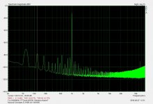
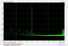
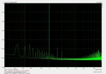
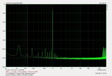
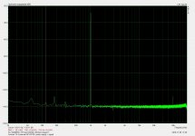
In all cases my comments were backed up with measurable improvements and client listening tests. Now I'm using the RTX 6001 for measurements which shows the changes in greater detail. Look at the attached results for his own amplifiers! You can see a drop in the noise floor, and all of the additional spikes in the "as found" tests compared to the completed corrections. I did not change the schematic on this. The improvements are in matching the diff pairs and correcting the ground wiring.
-Chris
I'm not trying to start a war here, but I have direct experience with both the stock Hafler amplifiers and preamps, and also the versions designed by John Hillig. In every case, the original Hafler circuit is superior. The preamp designs are quite frankly completely botched, and are actually Hafler circuits with the buffer stage removed! The parts weren't even matched closely enough. The same issues go for the power amplifier designs.
It took a bit of work, but I was able to make the preamp stable and sound better. I had to increase some transistor case sizes to lower their case temperature as well as lower the standing current. The dual power supply option was just plain stupid, and improvements to the regulators allowed a single outboard supply to be used.
The Musical Concepts amplifiers mounted the main filter capacitors upside down using the terminals for support! In addition, I had to make some small circuit changes and completely rework the grounds to make them listenable.
My honest appraisal would be to avoid these "upgrades" like the plague. You can do better by properly servicing those original boards, and by matching the transistors. Its the matched diff pairs that make a Hafler (and most any other amplifier) perform at the high levels of performance you are after. There is no need to greatly increase the supply capacitance. Stick with capacitors that fit in the original clamps. Use original sized capacitors on the PCB, higher voltages will give you a better quality capacitor. I can't stress enough how far matching all the transistors will bring you.
Hi Rick,
I'd love to see your work sometime. I don't have a hafler 200 or 220 in here at the moment, but if it is the same schematic you should have a winner there. Did you use any of the smt matched input pairs that are available? That would boost performance. I can match smt transistors, but it is a giant pain in the rear end to do.
Hi msb64,
I don't recommend bridging amplifiers, and the Haflers are included in that statement. You will cut your damping factor in half right off the bat. If you want a real positive boost in performance, go with an electronic crossover and run each drive off it's own amplifier. You will gain in efficiency right away, and the drivers then enjoy full damping. If you do that, I doubt you will ever go back to a normal setup in your main listening system.
In all cases my comments were backed up with measurable improvements and client listening tests. Now I'm using the RTX 6001 for measurements which shows the changes in greater detail. Look at the attached results for his own amplifiers! You can see a drop in the noise floor, and all of the additional spikes in the "as found" tests compared to the completed corrections. I did not change the schematic on this. The improvements are in matching the diff pairs and correcting the ground wiring.
-Chris
Attachments

Great info Chris, as usual! For what it's worth, my work so far on my 220 has followed exactly what you said.. I've replaced parts with new/upgraded parts of the same or similar values and have improved the grounding.
It's not surprising to me. I asked the original question, but am always very skeptical of these "improvements" especially when they take the form of completely redesigned circuits.
David Hafler was a legend, making dramatic sonic improvements on his circuits would logically seem to be a bit of a task. Especially by people who.... we'll for lack of a better word "aren't David Hafler."
Making small improvements by upgrading to better parts and getting components that are aging back into specs seems like a good idea.
Maybe eventually going to something designed by Bob Cordell could be an improvement. He has demonstrated a vast knowledge on par with the likes of Hafler. But before I make that plunge, I need to see some concrete evidence that it is indeed an improvement.
In the meantime, I'll fire up my 220 and listen to some tunes while I work on my new Pass F5 Turbo
Also - Thanks for all your help on my Adcom 565's!! Those bad boys are really working well and sounding great!
gabo
Hi gabo,
I'm glad this helped.
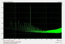
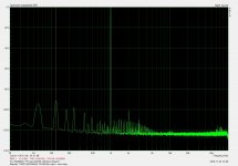
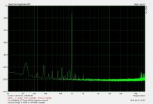
My definition of upgrading a piece of equipment is to make minor changes to the schematic at the most. If it does retain the sound character that it had before, it isn't an upgrade, but rather a different beast all together. These amps and preamps are well worth upgrading with normal, industry parts. I seldom use an audiophile darling part du jour, only when it is an industry accepted part (as in all industry, not just the audio folks). The upgrades I made on these amplifiers, and on the customer's preamplifier (using the teflon PCBs from Musical Concepts) made them just listenable. They were an enormously improved set of equipment compared to their "factory" configuration. The customer in this case would have been happy with a set of Hafler preamp and power amps, but he opted for Marantz 3250 and a pair of 170DC power amplifiers. A massive upgrade over the musical designs. I'll have to admit that I upgraded the Marantz equipment also, but even stock they out performed the Musical Concepts products. This system went from "active bi-wiring" (what is that?) to an active crossover type system (Furman TX-4 I upgraded). So even on the same speakers, the upgrade this customer had in his life were beyond his wildest expectations. He went to Marantz product at the urging of a mutual acquaintance who had a very good idea of what the upgrades would do. Now he wants an active crossover (a Furman also). To be fair, the Furman got a new shielded power transformer mounted on the outside and a two stage regulator for each channel along with the internal upgrades I made. I've included one report for the current performance of that crossover. Pretty darned good now, wouldn't you agree? This represents both power supply upgrades and internal audio path upgrades. An earlier upgrade to the power supply is still being used with the additional regulator. The new internal regulator I just installed hasn't been measured yet, but is very close to the one pictured using the external HP 6237B supply with 3' leads.
-Chris
I'm glad this helped.
My definition of upgrading a piece of equipment is to make minor changes to the schematic at the most. If it does retain the sound character that it had before, it isn't an upgrade, but rather a different beast all together. These amps and preamps are well worth upgrading with normal, industry parts. I seldom use an audiophile darling part du jour, only when it is an industry accepted part (as in all industry, not just the audio folks). The upgrades I made on these amplifiers, and on the customer's preamplifier (using the teflon PCBs from Musical Concepts) made them just listenable. They were an enormously improved set of equipment compared to their "factory" configuration. The customer in this case would have been happy with a set of Hafler preamp and power amps, but he opted for Marantz 3250 and a pair of 170DC power amplifiers. A massive upgrade over the musical designs. I'll have to admit that I upgraded the Marantz equipment also, but even stock they out performed the Musical Concepts products. This system went from "active bi-wiring" (what is that?) to an active crossover type system (Furman TX-4 I upgraded). So even on the same speakers, the upgrade this customer had in his life were beyond his wildest expectations. He went to Marantz product at the urging of a mutual acquaintance who had a very good idea of what the upgrades would do. Now he wants an active crossover (a Furman also). To be fair, the Furman got a new shielded power transformer mounted on the outside and a two stage regulator for each channel along with the internal upgrades I made. I've included one report for the current performance of that crossover. Pretty darned good now, wouldn't you agree? This represents both power supply upgrades and internal audio path upgrades. An earlier upgrade to the power supply is still being used with the additional regulator. The new internal regulator I just installed hasn't been measured yet, but is very close to the one pictured using the external HP 6237B supply with 3' leads.
-Chris
Attachments
- Home
- Amplifiers
- Solid State
- Hafler DH-200/220 Mods