Thanks, Bob.
So in theory, if all the 2SK134s are labeled 3, two of the 2SJ49s are 3, and two 2SJ49s are 4, should the 2SJ49s match up per channel or across channels?
In other words, when I remove the devices and reattach them with the new boards, should I move the 2SJ49s around (swap green or swap yellow in the photo)?
Both 2SJ49's on a given channel ideally should have the same number. By the same token, but 2SK134's for a given channel should have the same number (which might not be the same number as on that channel's 2SJ49's.
Cheers,
Bob
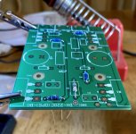
So I’ve been progressing through soldering components to the PCBs. Both OPS boards went smoothly. Simple work. I got frustrated with the little TO-92 transistors on the AFE boards. Tight spaces for my ham-fisted soldering.  Until this point I’ve been soldering both sides of the PCB, except for the caps.
Is it OK to solder these just from the bottom side of the PCB?
Until this point I’ve been soldering both sides of the PCB, except for the caps. Is it OK to solder these just from the bottom side of the PCB?
In disassembly of the old DH-220 boards, I’ve discovered that the old L1 coils are not the same between channels, nor do they match the description of the new DH-220C L1 coils.
So, I’ll have a go at making my own. What is the diameter and inductance value of the DH-220C coils? I know the build instructions describe how to make them, I just want to make sure I have the right target values.
So, I’ll have a go at making my own. What is the diameter and inductance value of the DH-220C coils? I know the build instructions describe how to make them, I just want to make sure I have the right target values.
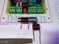
The DH-220C schematic shows the L1 coil inductance as 1.4uH which is the same value for the coil on the original PC19 board. For some reason, the coils on my PC19 boards have 13 turns vs 10-11 turns. I don't think the value is too critical, just as long as you're in the ball park. One suggestion is to take the PC19 coils and modify them to have the 10-11 turns.
One of my old coils is probably good, and looks like you describe from the PC19. But the other is thinner wire, and less turns.
I just want them to be as similar as possible in my amp, so I will make 2. I doubt I would be able to get a coil as neatly wound as the “good” original.
And thanks for pointing out the 1.4 uH. I saw that after I posted.
I just want them to be as similar as possible in my amp, so I will make 2. I doubt I would be able to get a coil as neatly wound as the “good” original.
And thanks for pointing out the 1.4 uH. I saw that after I posted.
In disassembly of the old DH-220 boards, I’ve discovered that the old L1 coils are not the same between channels, nor do they match the description of the new DH-220C L1 coils.
So, I’ll have a go at making my own. What is the diameter and inductance value of the DH-220C coils? I know the build instructions describe how to make them, I just want to make sure I have the right target values.
The value of the inductance is quite uncritical. Anything in the range of about 1.3 uH to 2.0 uH is fine.
Cheers,
Bob
I made my 18 gauge coils and soldered them in.
While I’m waiting for my new TO-3 sockets to arrive (I melted one during wire removal ) I ran through simple DMM tests of the Hitachi mosfets following this great post by ilimzn:
I’m guessing they all passed, though my diode drop readings were 300-400 mV.
Keeping my fingers crossed. I’ll keep pushing forward and with luck may have everything buttoned up for full amp testing over the weekend.
While I’m waiting for my new TO-3 sockets to arrive (I melted one during wire removal
) I ran through simple DMM tests of the Hitachi mosfets following this great post by ilimzn:ilimzn said:To measure an Nch MOSFET:
1) Use DVM in diode test position
2) Holding red lead on S
3) Put put black lead on D. Reading should be between 500 and 800, you are measuring the forward voltage drop in the body diode.
4) Put black lead on G. Reading should be 1... (open circuit)
5) Hold black lead on S
6) Put red lead on D. You shuld read 1... (open circuit) as the gate should be retaining negative charge from step 4.
7) Put red lead on G, you should read 1... (open circuit)
8) Put red lead backon D, you should read a low value (close to zero initially, possibly rising very slowly). You are now measuring the D-S voltage drop with the gate positively charged in step 7.
In any case, source to gate and drain to gate should alsways read open circuit. If you get low readings in steps 4 or 7, it's dead for sure (in either case, not a MOSFET... any more
I’m guessing they all passed, though my diode drop readings were 300-400 mV.
Keeping my fingers crossed. I’ll keep pushing forward and with luck may have everything buttoned up for full amp testing over the weekend.
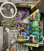
Your new DH-220C boards look good! The UFG series caps are a good choice if they fit. I assume they are the 470uf size which are 35.5mm tall. If you cannot make them work by leaning them sideways, Rick reported good results with the UBY series which you can get in larger uf values that will fit. Concerning your original Sangamo white power caps, those things should be replaced being 30+ years old. They will hinder your amp’s performance and are a reliability issue. I replaced the original caps in my DH500 upping them from 20k to 39k uf and heard a nice improvement in both bass response and dynamics. I believe you can get 22-24k uf value that are the same physical size as the original 10k for your DH220. When you do that, replace the flimsy wire between the power caps with heavier gauge wire or even copper rod. There is a lot of current flowing between the power caps. The wire from there to chassis ground should be heavier gauge wire as well. Some previous posts cover this. With the larger power caps, probably should add a thermistor on the AC supply to limit current at initial power up to reduce the load on your transformer and power switch for reliability. After the thermistor heats up and the power caps are charged, it will reduce resistance to not limit current flow.
Thank you!
I will likely do the big cap upgrade as 2.0 after this first phase of work. The old Sangamo caps measure well (cheap transistor tester from amazon) and the amp sounded actually great before I started this upgrade.
I managed to lay one gold nichicon down on one board and am about to do the next. However I somehow scratched the bottom of the board in the process, or didn’t notice this before. Are these little scratches a problem?
Attachments
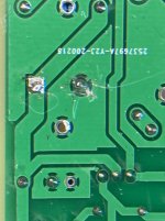
Those scratches appear to be to the outer clear coating and not the metal traces so should not cause a problem.
As for the power caps, the old caps can be a reliability issue and potentially fail unexpectedly causing damage to the amp and possibly your speakers. Plus, replacing the caps is one of the single largest improvements in sound quality you can make. So don't wait too long for upgrade 2.0.
As for the power caps, the old caps can be a reliability issue and potentially fail unexpectedly causing damage to the amp and possibly your speakers. Plus, replacing the caps is one of the single largest improvements in sound quality you can make. So don't wait too long for upgrade 2.0.
- Home
- Amplifiers
- Solid State
- Hafler DH-200/220 Mods