If I can't get a good signal like this, do I remove all of the outputs or just one? Do I put the capacitor from gate to source?

That looks OK.
Check the drive for the other bank of FETs.
On pin 1 of the lower op-amp on the driver board, do you now have a triangle waveform? Just curious.
Check the drive for the other bank of FETs.
On pin 1 of the lower op-amp on the driver board, do you now have a triangle waveform? Just curious.


Is either one in differential mode?
If you connect a load across the speaker terminals, does either change (after the relay engages)?
If you connect a load across the speaker terminals, does either change (after the relay engages)?
If you connect a load across the speaker terminals, does either change (after the relay engages)?
Use differential mode for the gate drive.
Use differential mode for the gate drive.
Yes. There is generally no reason to switch out of differential mode, especially for the output stage drive signals. The positive probe will work the same as normal if the negative probe isn't used.
When I use both channels of the scope in differential mode, channel 1 on the gate and channel 2 on the source, the display is a straight line. The two probe signals seem to cancel each other out. I didn't think that I needed to invert channel 2 since I was using the (-) math function?
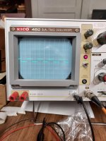
The photo is using the Micsig differential probe with the positive probe on the gate. The negative probe is unattached.
I am a little confused in that the Micsig has an X50 and an X500 setting, but my scope only has X1, X10, X100 and X1000.
I am using the X1 scope setting in this photo.
I will connect the load when I get this right.
Attachments

Try your other scope.
Use differential mode on the PS FETs to see if you get the expected waveform.
Use differential mode on the PS FETs to see if you get the expected waveform.

For the image above, which probe did you have on the FET source leg?
Set all cal knobs fully clockwise and increase the intensity for taking photos.
Set all cal knobs fully clockwise and increase the intensity for taking photos.

If you made the same connections to the output FET location, I have no clue how it was a negative waveform. An IRF640 can't be driven with a negative voltage.

- Home
- General Interest
- Car Audio
- Hifonics Brutus BRZ1200.1D