wrong!D stands for dielectric absorption
John Curl can provide information about the DA and its effects if he wishes - John Curl is quoted in the German trade journal "Elektronik", among others. In the 10/2003 issue, Helmut Lemme writes quite extensively about the "Dielectric Absoption", from page 91.
I believe this magazine, which not only developers in Germany receive free of charge (I have found it in my letterbox for over a quarter of a century without being asked), comes from Munich.
But an Internet search engine will also produce a correct result if you use it (or ask it).
#
Since this thread is actually about a circuit proposal from 1980, I will not explain the determination procedure (see MIL-C-19978D) of the DA and its meaning here. This is a separate topic and belongs in the components category.
kind regrads,
HBt.
Last edited:
Yes, you are right, I mixed that up.DA does not only stand for the dielectric absorption option in Germany (alone) - ancient measuring bridges do not determine this property of a capacitor!
It's nice that you recognize that. Unfortunately, that's not your only faux pas that I immediately noticed.Yes, you are right, I mixed that up.
Once again, I urge peace - and can do nothing more than offer the PM option.
thx
I don´t feel offended by that, it belongs to a normal discussion.It's nice that you recognize that. Unfortunately, that's not your only faux pas that I immediately noticed.
My good old M-25
Why did they use two high quality film caps on the input + a smaller one, if caps don´t matter? Why not just a 10 µF bipolar lytic?
Looking at the schematic those two caps are just cosmetic, there s other parts that are way more discutable
and sources of non linearities more important than those caps, electrochemical or polyprop doesnt matter here.
At distinct places I prefer film coupling caps.
Just because they grant very low leakage currents and tight tolerances compared to electrolytics.
And that's all, no audiophoolery mumbojumbo here.
And, btw, the underlying rules for choice of components in commercial designs are the biggest mystery in audio.
Do not expect to find the real explanation.
more often than not they do not make sense for the experts
Last edited:
Placeholder C1 = C2 may also be 47µF / 63Vdc, in parallel with a small foil type - as you wish.
The entire ensemble (marked in green, without C3) dynamically represents the working resistance of the BJT - locally and globally (feedbacked) within the loops. At 47µ the measured inner -3dB point is well below 1Hz (isolated observation in the open loop case without negative feedback, regardless of type)
The capacitors C1, C2 and C3 do not pose the slightest of problems in this circuit topology!
For more information on this thorny issue, see also:
" Elektor Ausgabe 11/1991
Audio-Kondensatoren (Auswahl von Kondensatortypen für Audioschaltungen) "
HBt.
Attachments
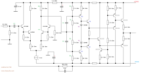
V_CE of the IP is constant, approx 1.45Vdc, modulated with a maximum of +/- 27mVac_peak. And that already represents the case where it is overdriven to the limit. The delta on the characteristic curve branch IC(VCE) is sufficiently minimal, to be able to do without any form of cascode (including current mirror) with a clear conscience. An overkill IP is completely excessive overzealousness in this, even the morphed topology (the concept). The selected BJT types of the original will also not suffer a CE breakthrough, that is impossible!
Now I ask for time,
because otherwise no one will create a PCB layout for this small, extraordinary amplifier - because we usually waste our time on trivialities.
As I said,
I would be grateful for any cooperation ...
kindly,
HBt.
Now I ask for time,
because otherwise no one will create a PCB layout for this small, extraordinary amplifier - because we usually waste our time on trivialities.
As I said,
I would be grateful for any cooperation ...
kindly,
HBt.
A good discussion is not a debate, in a discussion the discussants exchange arguments ...(...), it belongs to a normal discussion.
") .
.#
Apart from the oscillation argument (from which the original suffers just as much as from the TIM doctrine) and the inadequate frequency-compensation capability, the rest could be eliminated as irrelevant.
Dear Bernhard,
If you seriously want to make a contribution to improving the L.Stellema proposal - and you want to, after all, you have already posted your own personal idea and put the concept of morphing on the scales - then you must /should also feed MicroCap with the original. So far you have rejected this because you say it is not worth the effort, but only with this model (in the computer) can you start the optimization process. MicroCap in particular is predestined for this. You could juggle with the BJT etc. There are so many starting points that I don't want to list them. As an experienced developer, you yourself will know how to use this tool profitably - and your hobbyhorse, the THD, will not be neglected either.
This task would be an absolute gain for this thread, an enrichment. Perhaps you will reconsider your negative attitude in this regard. That would be great
With this in mind, I stand on the other side of the bridge that has just been built.
Greetings (and God's blessings),
HBt.
(I'm a big fan of the late Bob Ross, the joy of painting - a great and kind show, a kind man.)
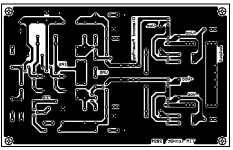
My first PCB, CAD/CAM project since the Corona breakdown. I was already afraid I wouldn't be able to do it at all ... And to create the right ambience for the 1980s design, I used an old DOS program: BoardMaker _1 (2 had a dongle), do any of you still know it? The Tim.zip file contains all the necessary files to make something reasonable / modern out of it: Gerber, Excellon, PS, PDF, LMD (for LPKF's circuit board plotter - milling) ..!
Please ask if anything does not seem to be self-explanatory. The PCB follows the schematic, it is directly readable - it becomes clear automatically on closer inspection.
Have fun with it,
HBt.
Please ask if anything does not seem to be self-explanatory. The PCB follows the schematic, it is directly readable - it becomes clear automatically on closer inspection.
Have fun with it,
HBt.
Attachments
The board dimensions are 100mm by 160mm; here is a film for exposure, for all those who would like to etch their board, drilling is done with 0.8mm as standard. The grid size is 2.54mm.
Attachments
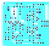
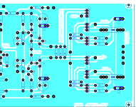
If you have any questions or if something doesn't seem self-explanatory, please let me know.
It's possible that there is no interest in testing this unusual amplifier, which teleported from 1980 to 2024 - and was modified during transport.
Or a luminary among today's KICAD layouters would like to take a look at the matter, who knows..?
Of course I haven't forgotten the heat sink.
Have fun with it,
HBt.
It's possible that there is no interest in testing this unusual amplifier, which teleported from 1980 to 2024 - and was modified during transport.
Or a luminary among today's KICAD layouters would like to take a look at the matter, who knows..?
Of course I haven't forgotten the heat sink
.Have fun with it,
HBt.
Placeholder C1 = C2 may also be 47µF / 63Vdc, in parallel with a small foil type - as you wish.
The entire ensemble (marked in green, without C3) dynamically represents the working resistance of the BJT - locally and globally (feedbacked) within the loops. At 47µ the measured inner -3dB point is well below 1Hz (isolated observation in the open loop case without negative feedback, regardless of type)
The capacitors C1, C2 and C3 do not pose the slightest of problems in this circuit topology!
For more information on this thorny issue, see also:
" Elektor Ausgabe 11/1991
Audio-Kondensatoren (Auswahl von Kondensatortypen für Audioschaltungen) "
HBt.
Pioneer use this VAS topology in a car amplifier that has switchable+-25-30V rails, although they use a classic EF2 OS
and an opamp instread of the differential.
That being said the low DC gain remain here as well as the dubbious ability of the IPS to DC drive correctly the VAS,
this could be remedied by puting a 1.2-1.3x voltage attenuator on the differential s buffers emitters such that the differential
emitters voltage are at about -5V.
What exactly are you afraid of wahab?
#
The Gerber format (BM1,2 uses) is very old, namely RS-274D; does anyone have an uncomplicated way of converting this into a suitable format, e.g. RS-274X, using also the drill file? Or a current full version of CircuitCAM (the TIM.cam file is loadable and complete), with which you can export all common formats?
Last edited:
hbt
I have many things to do including a long to do- and to try-list for my amplifier.
So I´m not thinking as deep into that topology as you.
As you know, my proposed schematic is noninverting.
I realized that both bases are at 0V permanently but did not think about the consequences.
The ips has static voltages at all times, so no cascode is needed, right.
The original schematic is an already well thought through concept, that is clear. Somebody put many effort in there. That it still has flaws, that should raise an eyebrow.
So I removed the cascode and the ccs in the inverting version of my schematic and distortion remains as low as before. So far, so good.
One point in the concept of that original schematic is that the value of the load resistor is very high, so a mirror is not really necessary, however:
I removed the mirror, changed resistors to 10k, K3 is now -150dB with mirror it was -174. So the mirror is still better.
The question for me would be: Could that topologie provoke any problems like unsatisfied stability that lead to a dead end ?
If I have time, I could sim that final schematic, but its not sure that I have all models.
Did you simulate that schematic with the 10pF? Is it stable?
Anyway, your build will reveal the truth.
Last edited:
In the computer, the topology with its dimensioning is extremely broadband and stable. Yes, I have simulated with and without Ck=10pf. In our case, Ck actually only determines the upper cut-off frequency f-3 or fh (fog in German).Did you simulate that schematic with the 10pF? Is it stable?
This applies to any test setup or experiment - and that's why I would like to point out that a proposal is only reliable when it has passed several test runs (has been practically rinsed), in the truest sense of the word "diagnostic".Anyway, your build will reveal the truth.
I also have a whole series of objections, or rather "concerns".
The experiment will either confirm them (and lead to practical solutions on the object) or not. However, it is not necessarily helpful to express all the concerns that one often justifiably has right at the start of a journey.
I have a checklist in the back of my mind and I work through it. If all my points on the list get a tick, then I confirm the function and release / let the fire /go.
It's not time yet.
However, this should not stop anyone from conducting their own experiments, quite the opposite - but you have to know that every experiment can go wrong.
Q1 to Q4, i.e. the actual VAS (in the submarine Tim thought), work at their power loss limits ..!
Just to raise one major concern. However, we can claim the Class A mode for advertising purposes, but we will not put the small BD203/4 power amplifier through this torture (which would also be complete nonsense in view of the Diamond configuration).
Yes:
you /we always have more in the back of your /our mind than just the obvious, there are many practical little things that are often forgotten in front of the computer or that you /we simply can't take into account yet.
So, that was my plea for the test setup, the practical test in the laboratory
.regards,
HBt.
At the moment, I'm more concerned that BM1 has not been able to generate an RS-274X. Unfortunately, I don't own TSIN's BoardMaker 3. Boardmaker 1,2,3 has a huge advantage over all other programs: you are not disturbed by anything in the actual design process and can devote yourself entirely to your creative work. This is identical to the old DOS or Win16 AutoCad, where the actual program does not interfere with the process.
So, how do I put the aperture list together with the NC data to create an RS-274X (or modern) file? Writing a program that implements this case as a command is more complex than starting a new layout with Eagle (but what about the licenses, are you allowed to make the complete files publicly available? I don't think so! So KiCAd after all - and I lack any motivation for that.
So I etch, but my printer is on strike and I only have limited access to a protomat (they are gathering dust now; everyone just sends their ideas overseas, costs apparently no longer play a role, regardless of whether the layout or the circuit actually works or is effective - just as a side note) at the moment. My construction will therefore also be delayed, but not forever.
#
And now back to "Tim".
- Home
- Amplifiers
- Solid State
- high performance 25W PowerAmp