Hornresp uses the traditional lumped-element electro-mechano-acoustical equivalent circuit loudspeaker model.
To learn more, Google is your friend...
There are, naturally, nuances to implementing the standard models, that I am afraid a simple Google search won't cover. This comparison between WinISD's and Hornresp's methods of calculating vented enclosures is a good example of such differences of interpretation: https://www.diyaudio.com/community/...tween-winisd-hornresponse.311268/post-5169553
Nevermind though. I was simply curious as to why your software, among the many "simple" (non-BEM/FEM) loudspeaker simulation programs, was the only one I know to show that difference. It's not that important. As I said, the basic assumption underlying the calculation is correct, but the scale is quite a bit off anyway.
If you search this thread you will find information as to the sources used for the calculations. Thiele, Small are not the only sources for accurate models for a Loudspeaker. The accuracy of Hornresp has continuously impressed me for the past 24 years of using it.With two identical tuned vents with different surface area (in the attached example 37,5cm² and 150cm² on a 10" speaker) on a bassreflex enclosure, all other parameters (including QL) being identical, in the small signal domain (2,83V in this case), Hornresp shows different sensitivities (only talking about the frequency area of the Helmholtz resonator, not the port's own resonances) for the two vents, with the larger vent being louder.
This is in principle correct, as I can testify having done my own extensive empirical research on the subject. But I am curious about your theoretical / mathematical model used in Hornresp for it to arrive at these results.
View attachment 1316697 View attachment 1316698
There are basically two approaches to simulating a vented box using a lumped parameter model. One is to use the equations from Small's and Thiele's papers, the other is to solve the actual equivalent circuit. The equations are derived from a simplified equivalent circuit and contain several assumptions, one of them is that the radiation resistance of the port is neglected. Hornresp solves the equivalent circuit, and that makes it possible to add refinements like including the actual vent radiation impedance (instead of just a simple end correction) and vent resonances. It is possible to add certain refinements to the equations as well, but this is seldom done.With two identical tuned vents with different surface area (in the attached example 37,5cm² and 150cm² on a 10" speaker) on a bassreflex enclosure, all other parameters (including QL) being identical, in the small signal domain (2,83V in this case), Hornresp shows different sensitivities (only talking about the frequency area of the Helmholtz resonator, not the port's own resonances) for the two vents, with the larger vent being louder.
This is in principle correct, as I can testify having done my own extensive empirical research on the subject. But I am curious about your theoretical / mathematical model used in Hornresp for it to arrive at these results.
The T/S equations calculate SPL from the difference between the driver volume velocity and the vent volume velocity (as was shown by Beranek to be proportional to SPL), while Hornresp calculates the actual power and pressure radiated by the driver and vent. Since the actual radiation impedances are used, instead of the equivalent mass, the effect of changing the vent area can be captured.
So in short, Hornresp arrives at these results by using a simulation method that has fewer assumptions that the simplified circuits or equations.
as was shown by Beranek to be proportional to SPL
Can you name / link to the exact source? Thank you.
The book Acoustics by Leo Beranek, McGraw Hill, 1954. Modern version: Acoustics: Sound Fields, Transducers and Vibration by Leo Beranek and Tim Mellow, Elsevier 2019.
Here is the relevant text from the 2012-edition of the Beranek/Mellow book:


Here is the relevant text from the 2012-edition of the Beranek/Mellow book:
Hi! Im new to hornresp and not very good in mathematics or speaker theory in general, so pleasy forgive me, but im trying to learn ")
I am going to build the Inlow 135hz Horn, and in time some conical horns for double 15incc drivers. This is my rig today:

but I have decided to try out conical midbasshorns, 15inch for 80hz-250hzish, and 8inch in inlowhorns for 250hz-600hz. I want to see if this can give more detailed male vocal pronouncement than 15inch alone. Im considering several options:

But for now im trying to simulate the 135hz Inlowhorns in hornresp to understand what parameters are good, and whats not.
I think this is fairly correct😬 Inlow135 with B&C8PE21


Now, the question:
1) Is Acustical impedencepeaks up to 1.6 and down to 0.4 in the midle of the work area considered good and yield good results?
2) How much electrical impedence in the workarea for the driver is tolarated/reasonable to expect in this case?
3) In my case the speakers are placed in the corner of the room, is it then more correct to use 1.0xPi settings?
I am going to build the Inlow 135hz Horn, and in time some conical horns for double 15incc drivers. This is my rig today:
but I have decided to try out conical midbasshorns, 15inch for 80hz-250hzish, and 8inch in inlowhorns for 250hz-600hz. I want to see if this can give more detailed male vocal pronouncement than 15inch alone. Im considering several options:
But for now im trying to simulate the 135hz Inlowhorns in hornresp to understand what parameters are good, and whats not.
I think this is fairly correct😬 Inlow135 with B&C8PE21
Now, the question:
1) Is Acustical impedencepeaks up to 1.6 and down to 0.4 in the midle of the work area considered good and yield good results?
2) How much electrical impedence in the workarea for the driver is tolarated/reasonable to expect in this case?
3) In my case the speakers are placed in the corner of the room, is it then more correct to use 1.0xPi settings?
Was the net box volume (including vent volume) the same for both models?With two identical tuned vents with different surface area (in the attached example 37,5cm² and 150cm² on a 10" speaker) on a bassreflex enclosure, all other parameters (including QL) being identical, in the small signal domain (2,83V in this case), Hornresp shows different sensitivities (only talking about the frequency area of the Helmholtz resonator, not the port's own resonances) for the two vents, with the larger vent being louder.
I think that the standard vented box calcs assume that the volume of air in the vent is much smaller than the net volume of air in the box. This assumption breaks down as the volume of the vent passes about 10% of the volume of air in the box. At about that point the shape of the box and the length and volume of the vent can affect final Fb, which can tend to be lower than expected if it was calculated using the typical vent length equation. We'd looked at that effect a few pages back in this thread.
Anyway, I was curious to see if we were just seeing the Iron Law in action. The total volume of a box with a given Vb but larger vent would be larger than that of a box with the same Fb but smaller vent.
Anyway, I was curious to see if we were just seeing the Iron Law in action. The total volume of a box with a given Vb but larger vent would be larger than that of a box with the same Fb but smaller vent.
@David McBean
I have a question.
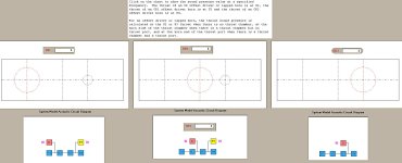
Is there a way to change the offset of the driver between different segments for a slot loaded closed transmission line with a offset driver as well as a offset port?
Like this;

By default this is always between S1 and S2
One might think to change that with the loudspeaker configuration menu.
But as soon as I do that, it's not the same system anymore.
In fact, and this might be a bug (?), but there is no way of getting this system back anymore at all?
I have a question.
Is there a way to change the offset of the driver between different segments for a slot loaded closed transmission line with a offset driver as well as a offset port?
Like this;
By default this is always between S1 and S2
One might think to change that with the loudspeaker configuration menu.
But as soon as I do that, it's not the same system anymore.
In fact, and this might be a bug (?), but there is no way of getting this system back anymore at all?
At about that point the shape of the box and the length and volume of the vent can affect final Fb, which can tend to be lower than expected if it was calculated using the typical vent length equation.
Fb was the same for both boxes, as you can see in the comparison of the impedance curves I posted. It's hard to see the graph includes both curves, since they practically lie over each other.
I can't comment on the rest of what you wrote (not quoted), as I can't find any info on it in the Hornresp documentation.
For "plain old ODOP's", you just need to mind Fta/Clo and Fr/Ap carefully when changing LS configs. Every time you change an OD config, Clo is reset to Fta (open) and Ap is reset to Fr (sealed)--that's what makes it "become something else."@David McBean
I have a question.
Is there a way to change the offset of the driver between different segments for a slot loaded closed transmission line with a offset driver as well as a offset port?
Like this;
View attachment 1317575
By default this is always between S1 and S2
One might think to change that with the loudspeaker configuration menu.
But as soon as I do that, it's not the same system anymore.
In fact, and this might be a bug (?), but there is no way of getting this system back anymore at all?
Attachments
Not sure if you keep up with the Purifi Blog posts, but they recently posted measurements of a passive radiator enclosure using this technique with a dome tweeter as the "microphone".
https://purifi-audio.com/blog/tech-notes-1/spk16-reference-design-12
Attached is an excerpt of the relevant sections.
The method including use of dome tweeter to directly measure volume velocity was published in AES article by Richard Small in 1972
AES E-Library Simplified Loudspeaker Measurements at Low Frequencies
Attachments
Hornresp Update 5610-240603
Hi Everyone,
CHANGE 1
The following cosmetic changes have been made to the Hornresp Help file:
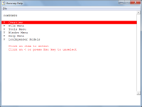
a. The Contents highlight bar now has a red backcolour and white forecolour as shown in Attachment 1. (Previously the highlight bar was light green and black).
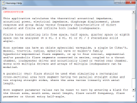
b. Section headings are now red, as shown in Attachment 2. (Previously the headings were black).
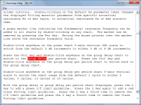
c. Search text found using the Find tool is now highlighted in red and white as shown in Attachment 3. (Previously the highlight colours were light blue and white).
CHANGE 2
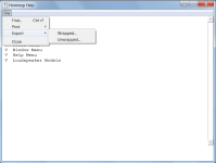
The Hornresp Help file can now be exported with the contents either Wrapped or Unwrapped. The wrapped file has a format similar to that of the document shown in the Help window, and cannot be readily altered. The unwrapped file has a format that can be modified by the user if required. Attachment 4 refers.
CHANGE 3
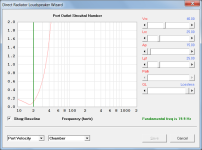
Double-clicking on the loudspeaker wizard port outlet velocity chart with the Ctrl key pressed now switches to a chart showing the Strouhal number vs frequency. Double-clicking again switches back to the port outlet velocity chart. Attachment 5 refers.
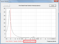
The Strouhal number is now also shown when port outlet particle velocity chart results are sampled. Attachment 6 refers.
See the thread linked below for background information. For further specific details on the Hornresp Strouhal number feature, search for the text string stro (the minimum required) using the Help File > Find tool.
https://www.diyaudio.com/community/...d-port-geometries.388264/page-30#post-7697621
BUG FIX
The run-time error bug detailed in Posts #14,753 and #14,754 has now been fixed.
My thanks to Rademakers for making me aware of the problem.
Kind regards,
David
Hi Everyone,
CHANGE 1
The following cosmetic changes have been made to the Hornresp Help file:
a. The Contents highlight bar now has a red backcolour and white forecolour as shown in Attachment 1. (Previously the highlight bar was light green and black).
b. Section headings are now red, as shown in Attachment 2. (Previously the headings were black).
c. Search text found using the Find tool is now highlighted in red and white as shown in Attachment 3. (Previously the highlight colours were light blue and white).
CHANGE 2
The Hornresp Help file can now be exported with the contents either Wrapped or Unwrapped. The wrapped file has a format similar to that of the document shown in the Help window, and cannot be readily altered. The unwrapped file has a format that can be modified by the user if required. Attachment 4 refers.
CHANGE 3
Double-clicking on the loudspeaker wizard port outlet velocity chart with the Ctrl key pressed now switches to a chart showing the Strouhal number vs frequency. Double-clicking again switches back to the port outlet velocity chart. Attachment 5 refers.
The Strouhal number is now also shown when port outlet particle velocity chart results are sampled. Attachment 6 refers.
See the thread linked below for background information. For further specific details on the Hornresp Strouhal number feature, search for the text string stro (the minimum required) using the Help File > Find tool.
https://www.diyaudio.com/community/...d-port-geometries.388264/page-30#post-7697621
BUG FIX
The run-time error bug detailed in Posts #14,753 and #14,754 has now been fixed.
My thanks to Rademakers for making me aware of the problem.
Kind regards,
David
Attachments
1) Is Acustical impedencepeaks up to 1.6 and down to 0.4 in the midle of the work area considered good and yield good results?
There is minimal ripple in the power response, so the peaks in the horn throat acoustical impedance are not a problem.
2) How much electrical impedence in the workarea for the driver is tolarated/reasonable to expect in this case?
The electrical input impedance should not be an issue.
3) In my case the speakers are placed in the corner of the room, is it then more correct to use 1.0xPi settings?
If tightly coupled to a corner, then 0.5 x Pi (eighth space) would normally be used.
In your case though, to be conservative I would probably just keep using 2.0 x Pi (half space) rather than 1.0 x Pi (quarter space).
Great, thank you!The Strouhal number is now also shown when port outlet particle velocity chart results are sampled.
I'm sure many will find this a very useful feature - I certainly do!
In your case though, to be conservative I would probably just keep using 2.0 x Pi (half space) rather than 1.0 x Pi (quarter space).
Thank you so much for your answers, it is indeed higly appriciated! Great!
Here is another question to all intermidiate users, and you McBean if you have the time:
Is there an practical guide anywhere online to design, say a Front Loaded Conical horn? If not, is there any of you guys who would like to share your usual procedure?
Often we DIYers have the maximum measurments (how big a horn can we build before our partner starts looking for new partners), and we have an idea of which driver we would like to use. So say that you fill in ca measurments, you then go into the Horn Loudspeaker Wizard, play around with S1 and S2, and the rear chamber values until the frequencyrespons is as flat as possible throughout the crossoverarea? Then you check the acustical impedence and make sure it is loading proprly, and dont have dips under 0.4? And then you.. -I don`t have a clue, im just guessing here, but it would be like manna from heaven for us beginners if someone could share their procsess including the values your seeking in Hornresp. -I know this is difficult becouse the optimal values probably depens on what you like sonicly, what kind of horntype, driver and so on. But if someone could just take an example of any frontloaded midbass horn I`m sure there is some kind of general knowledge to extract from the procedure your using.
It`s hard to find any practical info on horndesign, and I know, if you truly want to master it you have to learn everything including the mathemathics, but as it is in alot of other fields, im sure you can atleast get started with horndesign with a general and simplyfied understanding.
- Home
- Loudspeakers
- Subwoofers
- Hornresp