The tweeter in a Tannoy DC is a CD - it has to be bolted onto the back of the magnet to keep its VC in alignment, given that both 'drive units' use the same magnet / gap
AND Afaik all the 'newer' DC's have ferro-fluid in there as well, so un-bolting and removing the tweeter will turn the unit into 'bin fodder'...
Hi and thank you so much for the very valuable reply.
So it is not feasible. I have been impressed by the above post about the remarkable drop in distortion consequent to tweeter decoupling.
The idea was to place some of this sorbothane between the woofer magnet and the tweeter mounting frame, like just three washers of decoupling material in order to isolate mechanically the vibrating woofer from the tweeter and hoping for a decrease in distortion from the tweeter.
This looks a lot like my drivers ... of the Tannoy 609 mk II

This instead should be the tweeter frame (i have not unscrewed it yet).
An externally hosted image should be here but it was not working when we last tested it.
If i understand well you mean that placing 3 rubber washers between this frame and the woofer magnet in correspondence of the mounting screws will damage the driver ?
Or even a larger gasket around the horn maybe ?
This is very unfortunate indeed.
Thanks a lot again, gino
Last edited:
Well so far the decoupling of the mid driver with sorbothane seems less effective than it was on the tweeter...
I don't know if I have a mechanical short via my mounting screws and rubber rings or whether the sorbothane is just less effective damping the lower frequencies. Not the quick fix the tweeters were so I will get experimenting.
I don't know if I have a mechanical short via my mounting screws and rubber rings or whether the sorbothane is just less effective damping the lower frequencies. Not the quick fix the tweeters were so I will get experimenting.
What's transient response got to do with it ?
In the context of a decoupled midrange on a front baffle, some people are concerned with the midrange driver frame moving within its soft decoupling suspension. F = MA. For example, when the midrange cone accelerates forward, the midrange frame would move backward, compressing the soft decoupling material between the driver frame and the front baffle. This would impact the absolute motion of the midrange cone, rounding some of the transients. The movement is minuscule in a properly decoupled speaker while playing its designed range of frequencies.
Hi and sorry to jump in but if damping is key then at B&W with the Matrix concept they are quite wrong instead.
They brace extensively the cabinet to get high stiffness on the panels i guess
https://www.youtube.com/watch?v=IOnbkyjfQOI
Gino, the B&W 802 loudspeaker that you brought up is related to our discussion. The base enclosure looks similar to Panzerholz or Permali. Very stiff with good damping.
See the link:
https://www.youtube.com/watch?v=CnpIqyICl8Q
And the midrange enclosure is made of Marlan, a "Granite hard " synthetic mineral filled resin.
800 Series Diamond - Explore Bowers & Wilkins | B&W Speakers
Marlan solid surface solutions
The matrix structure inside the bass enclosure is interesting. I don't believe its primary function is stiffening, as this link and video mention damping also. The rigidity of the outer enclosure wall is much greater than the brace stiffness, so the additional stiffening by the brace would not be effective.
Bowers & Wilkins - Matrix
Loudspeaker Cabinet Bracing: Finite Element Analysis - Part II | Audioholics
Last edited:
Gino, the B&W 802 loudspeaker that you brought up is related to our discussion. The base enclosure looks similar to Panzerholz or Permali. Very stiff with good damping.See the link:
https://www.youtube.com/watch?v=CnpIqyICl8Q
Hi and i would like to thank you sincerely for the extremely klind and valuable help. It usually takes me a while before understanding even seemingly simple concepts.
But now i think i have understood. Stiffness and damping are equally important. And the material or composites that provide both are key for the construction of a good cabinet.
Impressive stuff from B&W indeed ... impressive.
But the layers they stick together only for pressure ? or they use some kind of glue in between the layers ?
And the midrange enclosure is made of Marlan, a "Granite hard " synthetic mineral filled resin.
800 Series Diamond - Explore Bowers & Wilkins | B&W Speakers
Marlan solid surface solutions
Again very impressive and also very beautiful. The fact that these speakers are used for mastering duties in some of the best recording facilities speaks for itself. A true masterpiece of a speaker.
The matrix structure inside the bass enclosure is interesting.
I don't believe its primary function is stiffening, as this link and video mention damping also. The rigidity of the outer enclosure wall is much greater than the brace stiffness, so the additional stiffening by the brace would not be effective.
Bowers & Wilkins - Matrix
Loudspeaker Cabinet Bracing: Finite Element Analysis - Part II | Audioholics
Maybe both ? it seems so.
Maybe if you say that
they could even use simple damping sheets applied on the outer enclosure and reach the same effect more easily. I really do not know. What i know is that B&W has put a lot of emphasis on the Matrix concept and use it in their TOTL creations.The rigidity of the outer enclosure wall is much greater than the brace stiffness

I am sure that the matrix bracing can add some extra structural robustness to the whole cabinet.
I do not know by the way if it floats inside or if it is glued to the outer enclosure.
I did not calculate the woofer back emission at the beginning.
I think that the test with a sthetoscope (i will buy one cheap and listen) can be extremely telling about the "cabinet sound"
I hope nobody will see me auscultating my speakers
I see already my mother asking me ... who are sick ? they or you ?

Thanks a lot again.
Kindest regards, gino
Last edited:
Hi Gino,
The stethoscope test has definately helped me. All my measurements seemed excellent with flat freq response on axis and smooth power response.
However all the measurements are taken directly in front of the drivers so the sound from the cabinet is overwhelmed by the direct sound. At the listening position though, I think the cabinet noise and reflections caused by radiated sound from the cabinet has more of an effect than my speaker measurements would imply.
I have now sorted the sorbothane with the mid-drivers too - with some larger rubber o-rings, and the whole sound from my speakers has changed.
I am not saying they sound completely different, but there is a slight change in the tone of them - I presume this is due to the reduction in the resonances from the cabinet - as we saw it reduced the output from the upper panel by up to 10 dB.
But also the sound stage is much better - I would say the best analogy is the 'focus' has sharpened, and the 'depth' has greatly increased. I presume this is due to less reflections and aberrant noise from the cabinets.
All this is highly subjective, but the stethoscope test is so different it dispels any worries that I am imagining such differences. I always thought a well damped, well braced, well stuffed speaker cabinet would be 'good enough'. It appears not!
Hi Gino,
The stethoscope test has definately helped me. All my measurements seemed excellent with flat freq response on axis and smooth power response.
However all the measurements are taken directly in front of the drivers so the sound from the cabinet is overwhelmed by the direct sound.
At the listening position though, I think the cabinet noise and reflections caused by radiated sound from the cabinet has more of an effect than my speaker measurements would imply.
I have now sorted the sorbothane with the mid-drivers too - with some larger rubber o-rings, and the whole sound from my speakers has changed.
I am not saying they sound completely different, but there is a slight change in the tone of them - I presume this is due to the reduction in the resonances from the cabinet - as we saw it reduced the output from the upper panel by up to 10 dB.
But also the sound stage is much better - I would say the best analogy is the 'focus' has sharpened, and the 'depth' has greatly increased. I presume this is due to less reflections and aberrant noise from the cabinets.
All this is highly subjective, but the stethoscope test is so different it dispels any worries that I am imagining such differences. I always thought a well damped, well braced, well stuffed speaker cabinet would be 'good enough'. It appears not!
Hi and thanks a lot for the very kind and valuable advice.
I have bought one cheap on ebay to try what you explain.
Your words on the voice now after the mods perfectly centered between the speakers is what has won me. This is the incontrovertible evidence that the mod works very very well .
I keep always at hand a test cd from Sheffield Lab that has a particular track recorded to test the soundstage rendition of the system.
I am sick for soundstage. Depth of soundstage in particular, of course.
It could be that some cabinet resonances in the mid-range were blurring the voice with distortion
I am quite sure that even a sweep could show this and probably you should be able to hear some peaks also with the stethoscope.
I think i also have somewhere a signal generator that i could use to find the exact points of resonance.
Unfortunately the absolutely best material for damping, lead, is also extremely toxic.
With a friend we glued and fixed with metallic staples some sheets of lead inside the panels of a speaker.
The boxes are now very heavy but very dead also and the effect on the bass is quite remarkable. But lead is as excellent as toxic so we are always looking for alternatives.
Anyway, also after watching the impressive video from B&W, i am convinced now that is not only a marketing idea but a real thing.
Thanks a lot again. Kindest regards, gino
Last edited:
Gino, understanding vibrations in general, and enclosure panel vibrations in specific, is not simple. Even those knowledgeable are left scratching their heads at times dealing with vibration problems in the field. Perseverance, caution, and humility are required. Testing, adjusting, and more testing is usually required to get good results, as Bushmeister has shown. Enclosure panel vibrations are closing related to the engineering field of structural borne noise and vibrations. My experience has been from the related rotating equipment side, pumps, fans, turbines, etc.Hi and i would like to thank you sincerely for the extremely klind and valuable help. It usually takes me a while before understanding even seemingly simple concepts.
Pause the video at the 9 and 13 second points, look closely and you will see alternating layers of material. Some are wavy and some are fairly flat. I presume some contain significant resins to enable bonding.But the layers they stick together only for pressure ? or they use some kind of glue in between the layers ?
http://https://www.youtube.com/watch?v=CnpIqyICl8Q
In the B&W video the spokesperson stated that the matrix was glued to the walls, assisting with damping. He also refers to stiffening. B&W may have implemented a new method of coupling and/or damping that we are not aware. I have measured internal bracing in loudspeakers vibrating significantly during impact and knuckle rapping tests, so I am leery of thin bracing. The rigidity of the outer enclosure wall is much greater than the brace stiffness, so the additional stiffening by the brace would not be effective.I am sure that the matrix bracing can add some extra structural robustness to the whole cabinet. I do not know by the way if it floats inside or if it is glued to the outer enclosure.
http://www.bowers-wilkins.com/Discover/Discover/Technologies/Matrix.html
See the table at the bottom of the first page on the link below. The natural resonance frequency of a panel can be greatly effected not only by the number of braces, but also by the stiffness of the braces themselves. The figure on the second page shows similar effects of stiffer braces.
http://www.audioholics.com/loudspeaker-design/detailed-look-proper-loudspeaker-cabinet-bracing/finite-element-analysis-part-ii
Last edited:
The bracing greatly impoves panel rigidity. I doubt this bracing is dampened at the wall interface, but rather solid mounted(glued), the "Matrix" is made in such a way that it itself provides the dampening. Look at the matrix picture in the link provided above. If you notice, the bracing is not continous from any one wall to the other. The controlled flexure of the matrix provides dampening of the panel modes. After the R&D costs are factored in these thin wood braces would be far cheaper than any other solution I am aware of. For example the solid aluminium bracing mentioned in the audioholics webpage is an extreme cost solution and not practical. If this was alum D channel it would cut costs considerably.
The one aspect I'm curious about is why they only braced horizontally. To break these modes would be much simpler if two vertical braces offset at ~1/3 and 3/5 makes far more sense imo.
The one aspect I'm curious about is why they only braced horizontally. To break these modes would be much simpler if two vertical braces offset at ~1/3 and 3/5 makes far more sense imo.
Last edited:
The rigidity is improved some, not as much as better methods. Guess we need testing results. Maybe its more effective at reducing vibration amplitudes, than raising panel resonance frequencies.The bracing greatly improves panel rigidity.
The spokesman in the link states "...The glued joints also add additional damping." Agreeing with you, even if the attachment joints use glue they still could be rigidly coupled and provide damping forces from the matrix.I doubt this bracing is dampened at the wall interface, but rather solid mounted(glued), the "Matrix" is made in such a way that it itself provides the dampening.
Do you have a good view of the assembled matrix, I'm interested.If you notice, the bracing is not continous from any one wall to the other.
This is what I was referring to before.The controlled flexure of the matrix provides dampening of the panel modes. After the R&D costs are factored in these thin wood braces would be far cheaper than any other solution I am aware of.
Agreed, the audioholics article was just stating a good technical point. And we, as DIY'ers, are free to use methods that are better technically but not necessarily economical, i.e. overkill. Yes, solid bracing is not the most efficient, maybe aluminum rectangular tube or I-beam.For example the solid aluminum bracing mentioned in the audioholics webpage is an extreme cost solution and not practical. If this was alum D channel it would cut costs considerably.
Agree with your question. I wonder if normal stiffening was the main purpose of the matrix.The one aspect I'm curious about is why they only braced horizontally. To break these modes would be much simpler if two vertical braces offset at ~1/3 and 3/5 makes far more sense imo.
Last edited:
Hi and thank you so much for the very valuable reply.
So it is not feasible. I have been impressed by the above post about the remarkable drop in distortion consequent to tweeter decoupling.
The idea was to place some of this sorbothane between the woofer magnet and the tweeter mounting frame, like just three washers of decoupling material in order to isolate mechanically the vibrating woofer from the tweeter and hoping for a decrease in distortion from the tweeter.
This looks a lot like my drivers ... of the Tannoy 609 mk II
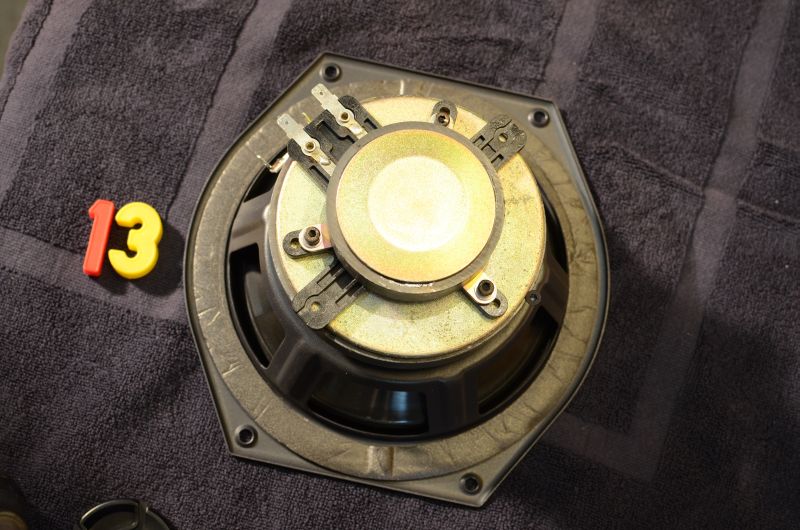
This instead should be the tweeter frame (i have not unscrewed it yet).
An externally hosted image should be here but it was not working when we last tested it.
If i understand well you mean that placing 3 rubber washers between this frame and the woofer magnet in correspondence of the mounting screws will damage the driver ?
Or even a larger gasket around the horn maybe ?
This is very unfortunate indeed.
Thanks a lot again, gino
Hmmm,
I was wrong, the tweeter is an individual..... things you miss when your only after a serial number
You could try some form of lossy mounting for the tweeter, though I'd start by putting the drive unit back together and into a less carply made enclosure and seeing how it sounds.
Bit like building a race car and setting it up for Brands Hatch when the thing has never been driven or run.....
Hmmm,
I was wrong, the tweeter is an individual..... things you miss when your only after a serial number
You could try some form of lossy mounting for the tweeter,
Hi ! thanks again for the very valuable advice
this is not my actual driver but looks pretty identical
I have not found a part no. on mine only in the web: 2040.
After reading all these advices to decouple tweeter from the baffle i was thinking to decouple the tweeter from the woofer ... maybe just adding some rubber washers between the tweeter mounting and the woofer magnet.
though I'd start by putting the drive unit back together and into a less carply made enclosure and seeing how it sounds.
Bit like building a race car and setting it up for Brands Hatch when the thing has never been driven or run.....
Yes the cabinet is cheaply built even if i like its shape
Better series like the Definition have a much better cabinet ... i have to stop but i see pair of Definition D500 and D700 on sale ... very beautiful speakers.
Anyway i feel this driver, even if it is not one of the best Tannoy DCs, has a potential for good sound.
It is quite powerful and exciting sounding.
A little harsh at time ... but i like it.
This weekend i will have a look at the x-over. If i find a electro cap in series with the tweeter it will end in the garbage bin for sure.
I am sure thi driver with the right x-over and a well made cabinet could be a spectacular monitor for home listening.
Thanks a lot again. Kind regards, gino
Last edited:
Patent for speaker enclosure with constrained layer damping.
https://www.google.com/patents/US5949033?dq=5949033&hl=en&sa=X&ei=LX7QVIr9KcTmsAT8mYGoCA&ved=0CB8Q6AEwAA
Patent for loudspeaker enclosure utilizing a rigid open-cell foam core
https://www.google.com/patents/US20090200102?dq=20090200102&hl=en&sa=X&ei=-H3QVIQcpbSwBLK6gNAI&ved=0CBwQ6AEwAA
Alusion and other open-cell aluminum foams may be useful for the types of enclosures discussed in the above patent 20090200102.
Stabilised Aluminum Foam, Aluminum Foam Panel, Aluminum Foam Core
http://www.creax.com/wp-content/uploads/creax/Bekaert-CREAX-MetalFoam.pdf
kind regards, jonathan
Excellent links the only issue I have is with:
"Decoupling the transducer from the cabinet is an undesirable approach because it prevents the transducer from utilizing the overall mass of the loudspeaker cabinet to minimize unwanted motion of the transducer frame. If the transducer is decoupled from the cabinet, there will be relative movement between the transducer frame and the cabinet"
As we have seen from various experimental results the 'relative movement' of the frame is insignificant, as is the loss of output from the driver. All decoupling does is prevent the mechanical energy from the driver exciting the cabinet and ultimately causing more vibration/distortion. It was interesting to note that the patent also suggested using sorbothane as a CLD layer.
I really like the concept of using structural open cell foam. But a little outside of my skill set!
Why build a complex, expensive, cabinet to damp mechanical energy from the driver, when simply de-coupling the driver achieves a more effective result?
Last edited:
Patent for loudspeaker enclosure utilizing a rigid open-cell foam core
https://www.google.com/patents/US20090200102?dq=20090200102&hl=en&sa=X&ei=-H3QVIQcpbSwBLK6gNAI&ved=0CBwQ6AEwAA
Thats Very interesting and it makes sense in parts.
I keep looking at using Closed cell pu foam, bare (but 'sculpted') on the inside with GF or CF lam'd on the outside. Biggest problem is cost of finding out how thick the foam walls should be.
Or how dense?
One could vary the density in laminations, but then the 'bonding' would interfere with (add) transmission.
I'll have to remember to take the patent to my 'foam man' next time I go, see what he thinks.
Gino,
could you send me a link for those D700's please (could save me a stink load of pain 'n' £'s)
If We're talking about the same D700 from the 90's, it's nothing more than a Very solidly built conventional box..... I know this because I've had me hands INSIDE one to find out.
I personally wouldn't bother making the HF unit mounting lossy, Tannoy don't (and I would say they are slightly more clued up than 'we')..... looking at the pictures further, making the mount lossy could cause it to vibrate in Unknown ways, due to the HF unit suddenly gaining an active Center of Gravity.
And wandering C of G's (there are many C of G's in an aircraft btw(not factoring in Center of Pressure shifts)) in an aircraft leads to Many interesting things.
Though one could try making the hf mounting lossy AND 'encapsulate' it with a lossy material to hold it - still too much 'ache' for maybe no gain.
I found some pics of the B&W 800 d's in 'sub assembly' form, reading what I see in the pictures, the curved cabinet walls laminated from veneers are most likely where the special properties lay (other than the 'whole'):
B&W Bowers&Wilkins 800s Craftsmanship
In other pictures of the 'matrix', one can see that the bias of 'horizontal material' is towards the rear.
The front baffle is bonded to the sides / top / bottom and though it Is bonded to the 'matrix', what contact there is is 'not a lot' compared to the rest of the structure.... If the matrix was Solidly (all things being relative) connected to the front baffle, it would make a very nice 'closed loop' for nasties to run round / through.
Front /Back motion of drive unit / baffle is directly transmitted to the cabinet Wall, which being laminated and curved provides a great 'sink' as it's construction is CLD.
The matrix then 'only' has to control the 'laminated wrap' which being CLD, means the matrix can be 'less' in terms of quantity as it has less to deal with.
The clever bit is getting the shape of the horizontal parts of the matrix 'correct' to provide the correct tapering of the braces so they 'sink' the 'whatevers' to the most highly stressed and dead part of the cabinet wall which is the tightly folded rear.
To me the current curved matrix construction makes more sense than the original, better use of physics and material etc etc.
@Ginetto,
I have an 8 inch tannoy DC and had be toying before with the same idea of "decoupling" the tweeter assembly too. However note that the transition between mouth of waveguide and speaker cone is crucial ( see Tannoy III LZ, on another tannoy) and by intoducing an offset due to the thickness of damping might create more problems than it solves. Maybe try what tannoy do on some of their monitors, there is a brace right behind the DC and a blob of "putty" pressed in between the tweeter magnet and the brace...
I have an 8 inch tannoy DC and had be toying before with the same idea of "decoupling" the tweeter assembly too. However note that the transition between mouth of waveguide and speaker cone is crucial ( see Tannoy III LZ, on another tannoy) and by intoducing an offset due to the thickness of damping might create more problems than it solves. Maybe try what tannoy do on some of their monitors, there is a brace right behind the DC and a blob of "putty" pressed in between the tweeter magnet and the brace...
It may be effective at reducing the forces driving the cabinet but if this comes at the price of introducing audible distortion it is not worth doing if the radiation from the cabinet can be reduced to below audible levels by other means.Excellent links the only issue I have is with:
"Decoupling the transducer from the cabinet is an undesirable approach because it prevents the transducer from utilizing the overall mass of the loudspeaker cabinet to minimize unwanted motion of the transducer frame. If the transducer is decoupled from the cabinet, there will be relative movement between the transducer frame and the cabinet"
Why build a complex, expensive, cabinet to damp mechanical energy from the driver, when simply de-coupling the driver achieves a more effective result?
A very rough feel for the relative size of the force introduced by the driver bouncing about on rubber grommets will follow from comparing the mass of the driver to the moving mass. For the midwoofer I looked up that was 2.2kg and 27g giving a bit over 1%. A more elaborate calculation using the properties of the grommet would give a more accurate picture of how this varies with frequency and when it is larger or smaller but it looks safe to say there will be an audible degradation.
Andy, True.
However, if you read through previous posts - measurements and in particular the link to the paper:
However, if you read through previous posts - measurements and in particular the link to the paper:
Loudspeaker Driver De-Coupling. A Preliminary report. A. Jones, Pioneer Electronics Tech.
A link to a paper concerning driver decoupling from Andrew Jones, Director of Engineering, TAD and designer of the TAD Reference 1.
http://www.linkwitzlab.com/Driver Decoupling.doc
A link to a paper concerning driver decoupling from Andrew Jones, Director of Engineering, TAD and designer of the TAD Reference 1.
http://www.linkwitzlab.com/Driver Decoupling.doc
Note that complete decoupling of any driver is impossible, but even is there is a 1% effect, this is a linear effect and does not necessarily lead to the assumption of a '1% sound degradation'. As Twinter has already said, the compliance of the decoupling material and the preload (compressive tightening by the screws) are important in ensuring there isn't degradation.
In fact, the transfer of mechanical energy to the cabinet would be much greater than 1% and unless this is completely removed by the cabinet (again impossible) the degradation would, in turn be much greater than 1% (even in a very well engineered cabinet).
Also, appreciate that rigid coupling of the driver to the cabinet, does not lead to a complete loss of driver movement. In fact, if you look at the above paper you will note that magnet acceleration impulse reponses are much worse with the driver coupled rigidly, (unless the cabinet is overwhelmingly rigid and massive.)
In my measurements you can see no increase in driver distortion measurable, but a considerable drop in cabinet induced distortion as a result of decoupling.
B&W, Eclipse, Magico etc. all use decoupling in their engineered solutions.
I agree there is no perfect solution, but you either absorb that mechanical energy at the driver/cabinet interface, or via the cabinet itself. One is much easier achieved than the other.
It is likely however, that a combination approach - as seen in the above mentioned designs is the best compromise.
- Status
- This old topic is closed. If you want to reopen this topic, contact a moderator using the "Report Post" button.
- Home
- Loudspeakers
- Multi-Way
- how to brace a speaker cabinet?