The test PCBs have been ordered.
I have updated the signup sheet with additional options relevant for balanced builds, and added pricing and BOMs for all boards. Please review your selections during the following week.
Link to signup sheet: https://docs.google.com/spreadsheets/d/1ARNwCxgBt8wAq6oHEUNPATnMsTOnYQita-9MakpxR7E/edit?usp=sharing
I will start sending out Paypal invoices during the second half of next week. If you have received an invoice, you can still change your order by contacting me by PM. I will not be checking updates to the signup sheet for the users who have received an invoice. Do not pay it if you want to change your order.
Short summary of available options:
Input board assembled kit:
One is needed per DAC build. It provides connectivity as described in the first post of this thread.
A typical configuration will require an unregulated 7-12V DC power supply. It can be used to power the input board, the USB interface, the attached microcontroller and the muting board. Other power options are possible.
A dual-DAM balanced build needs only one input board with additional connectors. The additional connector kits can be ordered together with input boards, they will not be sold separately. The connectors can also be obtained from other sources, see the input board BOM.
The input board stacks directly onto DAM1021. For balanced build, a second DAM1021 stacks on top of it.
Switch board assembled kit
The switch board is optional and is only needed to control DAM1021 by mechanical input switch and volume pot. It is not needed if the DAM will be controlled exclusively by a microcontroller via serial port.
One switch board is needed per DAC build, either standard or balanced.
Muting board
The muting board shunts the unbalanced outputs to ground via relay to prevent power-on and power-off plops produced by DAM1021. It implements 8 second delay during power-on, and AC detection for power-off.
Alternative balanced output buffers can be implemented on the muting board. Parts for the buffers will not be included.
An alternative muting control input can be implemented for driving it from DAM1021 pin18 or other external source. Parts for the alternative muting control will not be included.
The muting board stacks directly onto DAM1021. For balanced build, a second DAM1021 stacks on top of it. A balanced build needs one muting board with additional parts. The additional parts kits can be ordered together with muting boards, they will not be sold separately. The parts can also be obtained from other sources, see the muting board BOM.
Please see the BOMS for details on what exactly is included with each option and what additional parts need to be obtained for various builds. Note that the switch will be included with the switch board kit.
Input board BOM: https://docs.google.com/spreadsheets/d/1ENt40kTZhL9ITpYthZ8c4qUfL6y8ajTpFsxg7ic-8vU/edit?usp=sharing
Switch board BOM: https://docs.google.com/spreadsheets/d/1gz4L44eWwEkDHWcEnBIwdIYa3pOwWgeSbLcd3dcf6AY/edit?usp=sharing
Muting board BOM: https://docs.google.com/spreadsheets/d/1mkKxl3J7ERI1Ij2h5PFqQ5qZ6s5hMIRs1WoFZ5Vm1gg/edit?usp=sharing
When the test boards have been verified, I will provide more details on various build options and the needed power supplies.
Last edited:
Here is full schematic for the muting board with optional output buffers. The schematic contains parts for all possible build options. See the BOM for which parts need to be installed for each build option.
Attachments
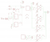
A clarification on possible muting board build options:
- It is possible to use the unbuffered outputs of a stock muting board with the optional balanced components added with a single DAM1021. It allows to assemble the muting board for balanced build, but add the second DAM later.
- The same goes for the optional balanced connectors for the input board.
- The unbuffered outputs are always available regardless of additional output buffers or single vs balanced configuration. The unbuffered output signal is taken directly from DAM J7 connector.
- The optional output buffers are mutually exclusive. Either SE-balanced (THAT1646) or true balanced (THAT1606) buffers can be build on a single board.
- A board built with SE-balanced buffers can be used in true balanced build, but there may be some performance degradation. The 5 kOhm input impedance of the buffers will be additional load to one channel, resulting in different loading of each channel. Only unbuffered outputs are useable in this scenario. This build type is not tested, use at your own risk.
- A board built with true balanced buffers can be used in single DAM configuration, but the unbuffered outputs will be additionally loaded with approximately 5 kOhm load. In this case there should be no imbalance, so the only effect should be some reduction of output level. Only unbuffered outputs are useable in this scenario. This build type is not tested, use at your own risk.
Normundss,
Firstly thank you for all the great work you have done with this. I know you have finalized this iteration but as the stock DAM really needs additional VRef capacitors for best performance I wonder if it would be possible to make a board (or a variation of the input board) which mounts on top of the DAM board and uses "nails" to connect to the Vref vias? If this was possible VRef capacitors could easily be accommodated and the board could also act as a shield for the R2R ladders. It would also make it much safer for less skilled diyers to add Vref caps. to Just a thought!
Best regards,
Paul
I don't think "nails" type connections can be made reliable enough for long term use. At least I am not aware of any solutions like that. Vref is supposed to be fixed in the latest DAM revision. So if you can't solder the Vref mods yourself and can't find someone to do it for you, there is still an option to sell the old DAM and buy a new one with improved Vref.
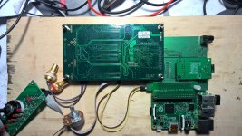
Meanwhile, the test PCBs are ready, I will be assembling and testing them this week.
Meanwhile, the test PCBs are ready, I will be assembling and testing them this week.
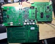
This is how it all looks together, top and bottom. The white wire sticking out from the dac is connected to U37 pin 18, the DAM mute control signal. It is not needed to use the muting board, but later I will test the option to use it.
The optional output buffers are not assembled at the moment.
The optional output buffers are not assembled at the moment.
Attachments

How about second DAC connection ?
Best
I will test it after I have verified that single dac works. The second dac will stack on top.
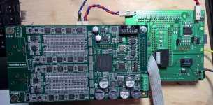
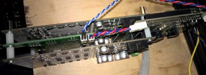
And a balanced dual dac assembly. I will provide better pics and description later, this is just so that people can get a feeling how it all goes together. It also gives an idea how the input board looks without a Raspberry attached.
Note that the J3 and J7 connectors are soldered on the bottom of the second DAM.
The muting board has a second relay, a top connector and an additional output header installed.
The input board has a top 2x13 connector for the second DAM, and a jumper for chaining the serial ports. The R1 resistor should also be removed if coax input is used, but I have not done it in here.
Attachments
HI Normundss,
The board looks great! Do you plan to provide cut out diagram for custom back panel?
Thanks,
The input board cutouts for back panel should be the same as for the V1.1 input board. The diagrams are in the PDF attachments on the V1.1 wiki page.
I have not yet verified the actual physical dimensions of V2 boards, so don't rush out to get the panels cut yet.
The cutout drawings with Raspberry Pi connections will come a bit later.
I would prefer to see a design that makes the actual board that connects to the dac's as small as possible, with nothing but a ribbon port for input signals and a 9 pin USB header that connects to the amanero. It would either connect bare either to your own connectors or connect to a ready-made PCB with these inputs, thus allowing full flexibility in chassis placement.
What I meant plainly was allow remote input connections, rather than have them fixed to the PCB attached to the dac's.
What I meant plainly was allow remote input connections, rather than have them fixed to the PCB attached to the dac's.
Last edited:
I would prefer to see a design that makes the actual board that connects to the dac's as small as possible, with nothing but a ribbon port for input signals and a 9 pin USB header that connects to the amanero. It would either connect bare either to your own connectors or connect to a ready-made PCB with these inputs, thus allowing full flexibility in chassis placement.
What I meant plainly was allow remote input connections, rather than have them fixed to the PCB attached to the dac's.
It is always a good idea to keep the I2S lines as short as possible, therefore the boards are directly stackable. A general rule of thumb is to keep I2S lines under 10cm long, and they are something like 5cm long when the boards are directly stacked. However, nothing prevents the use of ribbon cable to connect the input board to DAM1021. For a balanced build you would need a cable for each DAC.
Last edited:
I have tested the dual mono balanced setup and it works fine.
However, the test boards need a couple of small corrections for status indication lines. I will also adjust the layout of onboard voltage regulators to improve thermal management and allow attaching an optional heatsink. The heatsink is not needed for typical use, but may be required if the onboard regulators are used to power Raspberry Pi peripherals with high power consumtion, such as a large(-ish) display.
I will also make some tweaks to muting board layout to improve physical fit of some output buffer parts, and add pads for installing alternative capacitors for DAM output filter.
It will take another week to produce another test batch of modified boards, but overall the design works and we are getting closer to production run.
The second round of test boards is being manufactured and I hope they will not need any more corrections.
Initial draft of documentation can be downloaded here (PDF on Google Drive). More details will be added by the time the boards are being shipped out.
I will start sending out Paypal invoices soon. If you receive an invoice and want to modify your order, please send me a PM. I will not be checking the signup sheet for changes once an invoice has been sent.
The second round of test boards is being manufactured and I hope they will not need any more corrections.
Initial draft of documentation can be downloaded here (PDF on Google Drive). More details will be added by the time the boards are being shipped out.
I will start sending out Paypal invoices soon. If you receive an invoice and want to modify your order, please send me a PM. I will not be checking the signup sheet for changes once an invoice has been sent.
Where I could sign up for? I checked Wiki but it is not there.
Thank you
AR2
Where I could sign up for? I checked Wiki but it is not there.
AR2
Here is the online spreadsheet : https://docs.google.com/spreadsheets/d/1ARNwCxgBt8wAq6oHEUNPATnMsTOnYQita-9MakpxR7E/edit?pli=1#gid=0
Here is the online spreadsheet : https://docs.google.com/spreadsheets/d/1ARNwCxgBt8wAq6oHEUNPATnMsTOnYQita-9MakpxR7E/edit?pli=1#gid=0
Thank you!
Greatly appreciated. Yet, I just realized I was already on the list... Age does miracles. It must have been awhile I guess.
AR2
Last edited:
- Home
- Group Buys
- Input and switch boards for Soekris DAM1021 DAC