Hi normundss,
I am trying to trace an issue with the DAM losing lock. I have v1.1 input board but I am not using the front panel input board. Can I ask what the function of D1 is? I guess it is a back to back schottky diode? The cathodes of the back to back diodes are connected to an unused (by the front panel board) pin 6 on the input board connector J5?
D1 is there to allow the use of a single pole switch for input selection. It does nothing if you use the accompanying switch board or do not use a switch at all. It only affects the input select lines. If your DAM is on correct input, D1 is not the culprit.
Color OLED--1.8" Serial: UART/I2C/SPI True Color OLED160x128 OLED Module(CN) DS160128COLED-46...@normundss,
in the docs you have shown a picture withe a Dipole OLED (Figure 14), can you please give me some more info about this like a part number or something else?
Thanks!
It does not really have anything to do with DAM or the input boards in itself. You would have to write some software on raspberry to display something.
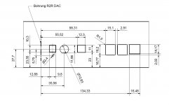
Thank you for sharing the mechanical drawings.
Keep in mind that isolation needs to be maintained when mounting the USB inputs on the back panel. Assuming the DAM1021 power supply ground is connected to the metal case (which it should be), the USB input and all Raspberry ports need to be isolated from it. Make sure the opening size allows it.
Keep in mind that isolation needs to be maintained when mounting the USB inputs on the back panel. Assuming the DAM1021 power supply ground is connected to the metal case (which it should be), the USB input and all Raspberry ports need to be isolated from it. Make sure the opening size allows it.
Thank you for sharing the mechanical drawings.
Keep in mind that isolation needs to be maintained when mounting the USB inputs on the back panel. Assuming the DAM1021 power supply ground is connected to the metal case (which it should be), the USB input and all Raspberry ports need to be isolated from it. Make sure the opening size allows it.
Just lift everything powering the dac with diodes/10R/0,1uF from the chassis and your have no problem even if the USB input should touch the chassis.
Just lift everything powering the dac with diodes/10R/0,1uF from the chassis and your have no problem even if the USB input should touch the chassis.
Depending on what is considered "no problem". What you suggest will work, of course, but all the ground noise from USB bus will get coupled into DAM circuitry, practically removing any benefit from the isolators. 10R//0.1uF is almost like direct connection for HF noise...
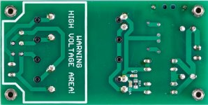
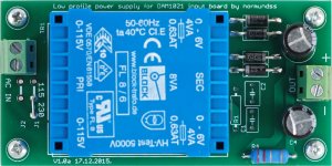
Here is an updated power supply PCB design. It allows to use larger rectifiers.
The BOM is here: https://docs.google.com/spreadsheets/d/1JSQe4oLrP-48RUtvBtkkBYZrWAU63KZXvamnQo9BDqQ/edit?usp=sharing
I have also updated the input board documentation. It is linked from the first port of this thread.
The power supply PCBs have arrived, they work fine. I have a few extra PCBs, send me a PM if you want one. The price is 12 EUR including shipping anywhere in the world, or 7 EUR if included with other Group Buy items. Or you can order them yourself from the files posted in #325.
I also have some PCBs for LT1963A based dual regulated supply for DAM1021. Have not had time to test them yet, will post the designs when they have been verified. A few of these PCBs are also available, the price is the same as above.
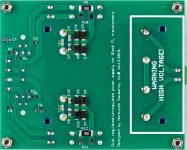
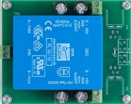
Here are the technical details for the dual LT1963A supplies that can be used for powering DAM1021 or other purposes.
The BOM is here: https://docs.google.com/spreadsheets/d/1rvS4O6W_eCkXdsCp5bpzkvgX6OqC4-43A-o3Ii4S_2I/edit?usp=sharing
The specified voltage setting resistors R1/R2 and R3/R4 will result in about 8.55V output voltage. Please see the LT1963A datasheet for information how to calculate resistors for different output voltages.
The boards can be built as regulated or unregulated supplies, for use with external regulators. They will accept Block FL10 - FL30 series power transformers, and are hardwired for 230V input. Feel free to tweak the designs to accomodate different transformers and input voltages.
The two outputs are isolated. To use it as a bipolar supply, either install wire jumper J1, or run four wires from the supply and connect the midpoint at the load.
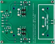
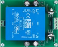
The builds in these pictures all have the optional SMD snubbers installed.
The BOM is here: https://docs.google.com/spreadsheets/d/1rvS4O6W_eCkXdsCp5bpzkvgX6OqC4-43A-o3Ii4S_2I/edit?usp=sharing
The specified voltage setting resistors R1/R2 and R3/R4 will result in about 8.55V output voltage. Please see the LT1963A datasheet for information how to calculate resistors for different output voltages.
The boards can be built as regulated or unregulated supplies, for use with external regulators. They will accept Block FL10 - FL30 series power transformers, and are hardwired for 230V input. Feel free to tweak the designs to accomodate different transformers and input voltages.
The two outputs are isolated. To use it as a bipolar supply, either install wire jumper J1, or run four wires from the supply and connect the midpoint at the load.
The builds in these pictures all have the optional SMD snubbers installed.
Attachments
-
 unregulated_digital_supply_bottom.jpg164.4 KB · Views: 312
 -
 unregulated_digital_supply_top.jpg209.8 KB · Views: 819
 -
 unregulated_dual_supply_bottom.jpg266.2 KB · Views: 833
 -
 unregulated_dual_supply_top.jpg240.6 KB · Views: 847
 -
 regulated_LT1963A_supply_bottom.jpg250.9 KB · Views: 882
 -
 regulated_LT1963A_supply_top.jpg258.4 KB · Views: 1,012
 -
Dual-LT1963A-1.0-eagle.zip79.3 KB · Views: 77
-
Dual-LT1963A-1.0-gerbers.zip45.3 KB · Views: 64
-
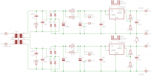 Dual-LT1963A-1.0-sch.png15.7 KB · Views: 356
Last edited:
The heatsink is not a clip-on type. It is supposed to be soldered to the PCB, transfering heat from the metal tab through PCB copper to the heatsink. It can be a bit tricky to solder properly without reflowing the whole board. The method that worked for me was to put some solder paste on the PCB heatshink pads, and to heat the heatsink in a grill oven to a high temperature, then quickly place it on the PCB where it melts the solder. If you don't put any chemicals on the heatsink before cooking it, it can be done in a kitched oven. I did prewarm the PCB a little with a hot air gun, but it may not be necessary.
However, the heatsink is only required in some specific cases when high-ish unregulated input voltage is used in conjunction with large external loads on the 5V supply.
If you use the recommended 7V supply for the input board with 5V output powering muting relay and a Raspberry Pi with display, there is no need for a heatsink.
If you use a 12V supply for the input board and only power a USB interface and the input board itself, there is no need for a heatsink.
If you use a 12V supply and power a Raspberry Pi from it, then you will need a heatsink.
And of course, if you use 3.3V supply from Amanero, and don't need to power any 5V peripherals, then the input board does not need external power at all.
The V2.3 board does not work I2S-2 Raspberry Pi input if not plugged USB power to Amanero.
Can someone help me find instructions for Amanero EXT-POWER on the Amanero board?
Thank you.
To disconnect USB power from Amanero, and feed it from 3.3V pins, you need to remove the U2 LDO on Amanero board.
http://www.diyaudio.com/forums/vend...-i2s-384khz-dsd-converter-24.html#post3154336
http://www.diyaudio.com/forums/vend...-i2s-384khz-dsd-converter-24.html#post3154380
Amanero schematic: http://www.amanero.com/USB_E.pdf
Thank you.
I had problems with 352800 and 384000 with Amanero on V2.3 board.
Now with EXT-POWER continues to fail those speeds and also fails 192000.
I will try another Amanero.
I will check the 3xx speeds with my Amanero. It is possible that the data line EMI filters on input board in some cases are filtering out to much HF and interfering with highest data rates. 192k should definitely work.
How do you supply the 3.3V power? Through the input board regulators?
Yes, through the input board regulators.
192k at first had continuous resynchronization, finally stabilized and worked.
Ask a friend about his Amanero Board.
It has a little noise at low frequencies up to 1500 Hz. Mass noise problems my provisional installation (-130 dB noise). I need to improve this.
Raspberry Pi output is very low jitter with this DAM1021, the sound quality of Internet radio is great and I get to play my records NAS with very low jitter over other like AppleTV.
- Home
- Group Buys
- Input and switch boards for Soekris DAM1021 DAC