I have finally received all the missing parts, and the input boards should be ready for shipping by the end of this week. I have sent out paypal invoices to all the people on the waiting list.
If you have contacted me before, but did not get an invoice, or if you just want to buy the boards, please send me a PM according to the instructions in the first post of this GB thread.
If you have contacted me before, but did not get an invoice, or if you just want to buy the boards, please send me a PM according to the instructions in the first post of this GB thread.
I have finally received all the missing parts, and the input boards should be ready for shipping by the end of this week. I have sent out paypal invoices to all the people on the waiting list.
If you have contacted me before, but did not get an invoice, or if you just want to buy the boards, please send me a PM according to the instructions in the first post of this GB thread.
Can I order or is it too late?
Hello,
I'm having some troubles to get the I2S working thru the input board.
DIYINHK directly connected to the DAM works good, supplied by the iso_3.3v from the input board.
When connected thru the input board, the DIYINHK board looks to be running, clocks and data looks OK so far with my old HAMEG scope and iso3.3v is OK.
Problem looks to come from around the multiplexer SN74HC157PW. Using the selector from the front panel, low level is at 0 but high level looks a bit too low, barely 1.36V. It's below the minimum specified.
As I2S from DIYINHK is I2S#1, it needs high level to pass till the DAC.
I have been looking for a possible leak somewhere but signal I2S_SELECT is likely only connected to the FRONT_PANEL and the RPI connectors beside the data switch. I don't have RPI yet and even the front panel disconnected give the same result.
So with almost 2v drop across the 10k R4 resistor, it's almost 200uA going thru the trigger, which according to the doc is way over the specs.
Could the multiplexer dead ? Any idea ?
Laurent
Last edited:
Hello,
I'm having some troubles to get the I2S working thru the input board.
DIYINHK directly connected to the DAM works good, supplied by the iso_3.3v from the input board.
When connected thru the input board, the DIYINHK board looks to be running, clocks and data looks OK so far with my old HAMEG scope and iso3.3v is OK.
Problem looks to come from around the multiplexer SN74HC157PW. Using the selector from the front panel, low level is at 0 but high level looks a bit too low, barely 1.36V. It's below the minimum specified.
As I2S from DIYINHK is I2S#1, it needs high level to pass till the DAC.
I have been looking for a possible leak somewhere but signal I2S_SELECT is likely only connected to the FRONT_PANEL and the RPI connectors beside the data switch. I don't have RPI yet and even the front panel disconnected give the same result.
So with almost 2v drop across the 10k R4 resistor, it's almost 200uA going thru the trigger, which according to the doc is way over the specs.
Could the multiplexer dead ? Any idea ?
Laurent
Please check if there is 3.3V present on mux chip pins 8 and 16 (8 is GND, 16 is VCC).
Also check with a loupe if R4 is well soldered on both sides, and if there is any solder bridge between mux pins, especially near pin 1.
7sYFYbIBMgGoR7PD!~~_12.JPG?set_id=8800005007)
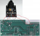
I would like to use this toslink with the normunds input board but what is the best way since the board uses a pcb mount.
I have this toslink and it's pretty good.
This should work:
Attachments
Please check if there is 3.3V present on mux chip pins 8 and 16 (8 is GND, 16 is VCC).
Also check with a loupe if R4 is well soldered on both sides, and if there is any solder bridge between mux pins, especially near pin 1.
3.298v on the chips 8 & 16 pins. No short between the pins.
I resoldered R4 in case and bingo, I have the right high level voltage.
But still, the DAM doesn't synchronize.
Tracking the signals from USB board to the muxer is OK on pins 6, 10 and 13.
Output is OK up to the capacitors. Bit clock and word clock are missing after.
2 of the capacitors are not soldered on one side.


That time it looks a bit more tricky, it seems some of the capacitors' ground connections are not soldered either. I'll try to get it right.
By the way I also found 3 other resistors soldered only on one side next to the leds PWR, F3 and F2. A monday morning board ?...

3.298v on the chips 8 & 16 pins. No short between the pins.
I resoldered R4 in case and bingo, I have the right high level voltage.
But still, the DAM doesn't synchronize.
Tracking the signals from USB board to the muxer is OK on pins 6, 10 and 13.
Output is OK up to the capacitors. Bit clock and word clock are missing after.
2 of the capacitors are not soldered on one side.
That time it looks a bit more tricky, it seems some of the capacitors' ground connections are not soldered either. I'll try to get it right.
By the way I also found 3 other resistors soldered only on one side next to the leds PWR, F3 and F2. A monday morning board ?...
you ordered a prebuilt board?
I hope mine will be fine. i'm not going to be very good at diagnosing these kind of problems. unless they are obvious like only one side of a cap is soldered.
Tracking the signals from USB board to the muxer is OK on pins 6, 10 and 13.
Output is OK up to the capacitors. Bit clock and word clock are missing after.
2 of the capacitors are not soldered on one side.
That time it looks a bit more tricky, it seems some of the capacitors' ground connections are not soldered either. I'll try to get it right.
By the way I also found 3 other resistors soldered only on one side next to the leds PWR, F3 and F2. A monday morning board ?...
Sorry about the bad board you got. I have to admit, this one looks exceptionally bad. If you don't feel like fixing up the bad joints yourself, you can send the board to me and I will fix it or replace it.
I did not catch these soldering problems on some boards in the initial shipments, the later ones are visually checked much more thoroughly. They all passed initial electrical tests, which is why I did not look so closely at first. The bad joints probably got oxidized and jiggled loose during shipping.
The chance of getting a current board with bad joints is pretty low.
In any case, I will help to diagnose and fix any suspect boards, or replace them if the buyer so chooses.
Btw, the boards for all currently paid invoices are getting shipped today.
Just to clarify: if I paid for an assembled kit - do I receive it with coax BNC and toslink soldered in or I need to add these by myself?Sorry about the bad board you got. I have to admit, this one looks exceptionally bad. If you don't feel like fixing up the bad joints yourself, you can send the board to me and I will fix it or replace it.
I did not catch these soldering problems on some boards in the initial shipments, the later ones are visually checked much more thoroughly. They all passed initial electrical tests, which is why I did not look so closely at first. The bad joints probably got oxidized and jiggled loose during shipping.
The chance of getting a current board with bad joints is pretty low.
In any case, I will help to diagnose and fix any suspect boards, or replace them if the buyer so chooses.
Btw, the boards for all currently paid invoices are getting shipped today.
Thanks
Just to clarify: if I paid for an assembled kit - do I receive it with coax BNC and toslink soldered in or I need to add these by myself?
Thanks
You will need to add those yourself, as well as an input transformer if you want to use the coax input.
The BOMs linked from the first post of this thread list all parts that are included and that can be optionally added for various builds. Farnell and Mouser part numbers are listed for most optional items.
In any case, I will help to diagnose and fix any suspect boards, or replace them if the buyer so chooses.
Thanx normundss for the proposal.
I finally got it right while I didn't feel very comfortable with these tiny components and no specific tooling to handle them.
No problem at all on the muting board.
Back to the implementation now.
You will need to add those yourself, as well as an input transformer if you want to use the coax input.
The BOMs linked from the first post of this thread list all parts that are included and that can be optionally added for various builds. Farnell and Mouser part numbers are listed for most optional items.
Has anyone covered doing an AES input?
I've not seen anyone do that yet.
Thanx normundss for the proposal.
I finally got it right while I didn't feel very comfortable with these tiny components and no specific tooling to handle them.
No problem at all on the muting board.
Back to the implementation now.
I hope it's ok to post this...but to help with the soldering of small components.. I found a way that is super easy for me. I recently did a bunch of tiny ndk clocks this way. those are 2x2.5mm, and a bunch of bypass caps 0805's
they look professional I think?

please see these youtube quick tutorials...
I used SRA low temp solder paste (hot air gun set to 200C, or 180C when doing ndk clocks), and a hot air gun with 3mm tip... + kapton tape for protection of surrounding components and prevention of solder spatter (for removals with chipquik)
example of smd IC
https://youtu.be/MqivHi7Qjvk
example of 0805 caps and oscillators, controllers, resistors and caps.
https://youtu.be/2Z7nCAxS2Rg
Again,this is sort of on topic,and I apologize if this is too much off topic. But I wanted to share a soldering technique that is pretty cool. instead of the old iron
Again, if this is too off topic, I will delete or remove this. If I need to do any repairs, I plan to approach this way. t
I am still quite new, but this technique has worked the best for me!!!
Has anyone covered doing an AES input?
I've not seen anyone do that yet.
Take a look to Lundahl 1574 ...
An externally hosted image should be here but it was not working when we last tested it.
_IMG_0928_kl.jpg)
I also would like to know more. as i'm going to be installing an HDMI i2s module from Audio-GD
the input module. I plan to feed the soekris from my DIU8 (xmos)that I modded with NDK clocks. and will output via hdmi output to the soekris hdmi input. I hope this is possible? proper wiring? wondering where all the pins would go on the input board, or ? i'll be using two dam1021's
I would love to compare direct i2s HMDI vs my waveIO
plus it's just nice to use my DDC to control all my dacs
http://www.audio-gd.com/Pro/diy/I2Skits/HDMISOC.JPG
Would someone show me the best way to hook this module up? To normundss input board?
Thank you!
An externally hosted image should be here but it was not working when we last tested it.
- Home
- Group Buys
- Input and switch boards for Soekris DAM1021 DAC