i guess tuning such a box may be a challenge!
another problem with tubes is they resonate from chuffing resonances, like a pan flute. this makes chuffing (of several ports) much more noticeable and annoying. In essence: you want to minimize the port edges.
I will show more investigation results in the next posts!
another problem with tubes is they resonate from chuffing resonances, like a pan flute. this makes chuffing (of several ports) much more noticeable and annoying. In essence: you want to minimize the port edges.
I will show more investigation results in the next posts!
Last edited:
my first optimization step was to see how the lower enclosure resonances can be dampened/absorbed.
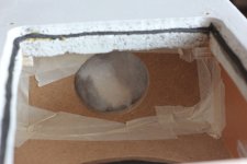
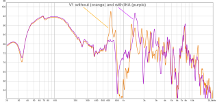
I first added basotect (melamine foam) to chamber 1 to dampen the longitudial resonance (660 Hz).
Optimum dampening occured when putting a strip of foam across the chamber with some distance to the back wall.
As i realized later this however also reduced bass output.
So I installed a small helmholtz resonator at the back of the chamber. Filling it with basotect on both sides and some polyfill in the center had the additional benefit of significantly reducing the port resonance (780 Hz).
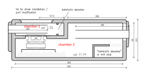
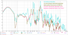
I also tried dampening and installation of a helmholtz resonator in the bigger chamber V2 to remove the resonance at 300 Hz. Basotect strips across the width of the box were again useful to dampen the resonance but also reduced bass output, so i went on to build a helmholtz absorber.
I could not install a simple board with central hole as in V1 and this made things considerably more complicated.
The small internal resonator enclosure changed the existing resonance(s). Also, the calculated resonance frequency of the internal helmholtz resonator was much different than expected by simple calculation, probably because the “port” ist near the enclosure wall and probably several other interactions with the whole enclosure.
The best results i could achieve were by opening half of the “helmholtz” resonator and putting a piece of basotect at the open surface of the little stub.
I guess V2 should now rather be called a mass loaded quarter wave resonator with some dampening in the lower end!
A general comment about internal helmholtz absorbers:
As far as I undestand the helmholtz absorber itself would not need any fibrous material to “absorb” sound and turn it into heat.
The absorber will instead create a 180° phase shifted pressure at the helmholtz frequency and thus does not even allow the resonance to build up.
Dampening material in the helmholtz absorber will lower the resonance frequency (by virtually increasing volume) and lowers and broadens the resonance peak.
This may be useful to have a wider absorption spectrum and/or to account for inaccuracies when trying to match the absorber exactly to the resonance peak. The latter is much more complicated than i expected. A helmholtz resonator inside a box will interact and obviously cannot be considered a separate element. Both the longitudinal resonance and the (theoretical) helmholtz tuning frequency will change once installed in the box.
As far as i experienced an internal helmholtz absorber works best in the longest enclosure dimension, having one central hole (as in V1 of my box). It definitely needs some tweaking by adjusting volume/port size/dampening.
A small and in maybe a bit simplified (german) description for internal helmholtz absorbers “IHA”:
https://www.der-akustische-untergrund.de/tipps-n-tricks/iha-berechnung-mit-basscade/
there was an additional resonance audible when tapping on the board below the driver. Strangely this resonance got much higher (360 Hz) when tightening the screws of the driver. I thought that a stiffening board might help, but did noch change anything.
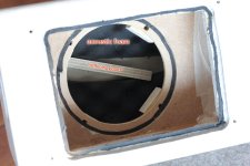
I could have added more dampening material on the walls etc. to reduce the higher resonances. But these are so far outside the usable bandwith that i did not continue here.
I first added basotect (melamine foam) to chamber 1 to dampen the longitudial resonance (660 Hz).
Optimum dampening occured when putting a strip of foam across the chamber with some distance to the back wall.
As i realized later this however also reduced bass output.
So I installed a small helmholtz resonator at the back of the chamber. Filling it with basotect on both sides and some polyfill in the center had the additional benefit of significantly reducing the port resonance (780 Hz).


I also tried dampening and installation of a helmholtz resonator in the bigger chamber V2 to remove the resonance at 300 Hz. Basotect strips across the width of the box were again useful to dampen the resonance but also reduced bass output, so i went on to build a helmholtz absorber.
I could not install a simple board with central hole as in V1 and this made things considerably more complicated.
The small internal resonator enclosure changed the existing resonance(s). Also, the calculated resonance frequency of the internal helmholtz resonator was much different than expected by simple calculation, probably because the “port” ist near the enclosure wall and probably several other interactions with the whole enclosure.
The best results i could achieve were by opening half of the “helmholtz” resonator and putting a piece of basotect at the open surface of the little stub.
I guess V2 should now rather be called a mass loaded quarter wave resonator with some dampening in the lower end!


A general comment about internal helmholtz absorbers:
As far as I undestand the helmholtz absorber itself would not need any fibrous material to “absorb” sound and turn it into heat.
The absorber will instead create a 180° phase shifted pressure at the helmholtz frequency and thus does not even allow the resonance to build up.
Dampening material in the helmholtz absorber will lower the resonance frequency (by virtually increasing volume) and lowers and broadens the resonance peak.
This may be useful to have a wider absorption spectrum and/or to account for inaccuracies when trying to match the absorber exactly to the resonance peak. The latter is much more complicated than i expected. A helmholtz resonator inside a box will interact and obviously cannot be considered a separate element. Both the longitudinal resonance and the (theoretical) helmholtz tuning frequency will change once installed in the box.
As far as i experienced an internal helmholtz absorber works best in the longest enclosure dimension, having one central hole (as in V1 of my box). It definitely needs some tweaking by adjusting volume/port size/dampening.
A small and in maybe a bit simplified (german) description for internal helmholtz absorbers “IHA”:
https://www.der-akustische-untergrund.de/tipps-n-tricks/iha-berechnung-mit-basscade/
there was an additional resonance audible when tapping on the board below the driver. Strangely this resonance got much higher (360 Hz) when tightening the screws of the driver. I thought that a stiffening board might help, but did noch change anything.

I could have added more dampening material on the walls etc. to reduce the higher resonances. But these are so far outside the usable bandwith that i did not continue here.
what happens if the port is mounted on the outside of the box instead of the inside?
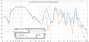
as to be expected the longitudinal resonance (influenced by IHA) has a pressure peak at the enclosure wall and exits the port.
so, it's good to keep interior port ends in the center of the box to avoid transmitting pressure peaks. I did not, however, check what influence (chuffing?) it has if the port protrudes into a velocity maximum in the box...
anyone ever wonderd why the ports seem to be blowig air out?
I didn’t and just thought that’s how vibrating air feels.
and of course a port should not blow air - where would all that air come from??
But in fact the port does indeed blow air! one can feel the port air flow even 1m away from the port!
It’s very easy to test with a sheet of paper or a small propeller using a loud sine at the box resonance frequency:
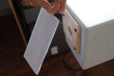


the paper is only actually vibrating (and slapping against the port) if held very close to the port exit.
The reason is: with higher pressure inside the box the port blows air straight out (directed flow from the port) but when the pressure in the box is lower than outside the air flows in from any direction around the port (and indeed mostly from the sides. by the way I don't think this has been addressed in the bezzola paper).
Moreover, with longer bass notes there is a constant flow of air starting just outside the center of the port and a return flow from around the port. I suppose for high levels this circular flow can be quite large!
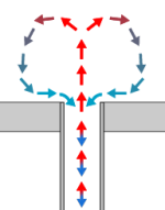
here is another small test:
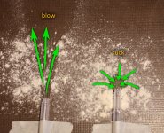
blowing air is directed and has a long throw in exactly one direction.
sucking air (i didn't - it was a vacuum cleaner!) collects air from all around the opening.
This is in accordance with my experiments. Chuffing is mostly being created by air flowing back into the port from the sides. Sharp edges or rough surfaces around the port exit create turbulences and noise.
Also, if the port does not easily allow free return air flow from the sides (sharp edge) the efficiency is probably reduced because more air (weigth) is coupled to the port vibration, but it's not a coherent directed flow like inside the port (that in that case would virtually prolong the port) and will cause losses and noise.
In my tests there were two main “chuffing” noises:
I didn’t and just thought that’s how vibrating air feels.
and of course a port should not blow air - where would all that air come from??
But in fact the port does indeed blow air! one can feel the port air flow even 1m away from the port!
It’s very easy to test with a sheet of paper or a small propeller using a loud sine at the box resonance frequency:


the paper is only actually vibrating (and slapping against the port) if held very close to the port exit.
The reason is: with higher pressure inside the box the port blows air straight out (directed flow from the port) but when the pressure in the box is lower than outside the air flows in from any direction around the port (and indeed mostly from the sides. by the way I don't think this has been addressed in the bezzola paper).
Moreover, with longer bass notes there is a constant flow of air starting just outside the center of the port and a return flow from around the port. I suppose for high levels this circular flow can be quite large!

here is another small test:

blowing air is directed and has a long throw in exactly one direction.
sucking air (i didn't - it was a vacuum cleaner!) collects air from all around the opening.
This is in accordance with my experiments. Chuffing is mostly being created by air flowing back into the port from the sides. Sharp edges or rough surfaces around the port exit create turbulences and noise.
Also, if the port does not easily allow free return air flow from the sides (sharp edge) the efficiency is probably reduced because more air (weigth) is coupled to the port vibration, but it's not a coherent directed flow like inside the port (that in that case would virtually prolong the port) and will cause losses and noise.
In my tests there were two main “chuffing” noises:
- port resonance being excited by turbulences. With bad ports and sine tones at speaker resonance frequency (high airspeed in the port) this is audible at very low levels.
- additional high frequency hiss produced at high levels.
- avoids turbulence at the port edges (exciting port resonances). this refers to both ends of the port.
- allows for a smooth airflow from the sides. this mainly refers to the exterior end of the port because it is more noticeable. but for efficiency it is probably also valid inside the box.
Last edited:
how audible is port chuffing?
I did a very informal test using a wave file composed of three parts:
lorde uses a synth bass that seems to be based on a pure sine or at least it’s heavily filtered, thus does not allow masking of distorsion with existing harmonics.
And the piece is in D and the lowest bass note is therefore 35 Hz (well, probably 36 Hz ...)!
Please keep in mind that the human ear is very unsensitive at such low frequencies and thus any distorsion is even more audible. So it’s a really tough test!
Here is a table with my subjective results from the straight, unflanged and undampened port(s), in about 1 meter distance from my ears.
For the music tests I added the (highpassed) fullrange speaker shown in post #19.
This was just a rough test – I did not care too much about a perfect system.
I also add objective data from REW measurements and hornresp simulation.
*) background noise!
I did a very informal test using a wave file composed of three parts:
- a -20 dB 35 Hz sine tone (35 Hz is more or less the tuning frequency of the bigger chamber)
- a 150Hz 2nd order low-passed excerpt of Lorde’s „Royals“; bass peaks at about -20dB.
- a fullrange version of the same music excerpt
lorde uses a synth bass that seems to be based on a pure sine or at least it’s heavily filtered, thus does not allow masking of distorsion with existing harmonics.
And the piece is in D and the lowest bass note is therefore 35 Hz (well, probably 36 Hz ...)!
Please keep in mind that the human ear is very unsensitive at such low frequencies and thus any distorsion is even more audible. So it’s a really tough test!
Here is a table with my subjective results from the straight, unflanged and undampened port(s), in about 1 meter distance from my ears.
For the music tests I added the (highpassed) fullrange speaker shown in post #19.
This was just a rough test – I did not care too much about a perfect system.
I also add objective data from REW measurements and hornresp simulation.
| amp output voltage (V rms) | Chuffing audible with sine? | Chuffing audible with low passed music? | Chuffing audible with fullrange music? | SPL dB @ 1m | REW measurement for sine tone noise “N %” | REW measurement for sine THD % | Hornresp simulated port velocity (m/s) / (% of mach1) | Subjective impression / remark |
| 0,5 | no | no | no | 61 | 4,95 * | 0,41 | 1,3 / 0,38% | Sine tone is barely audible! |
| 1 | no | no | no | 67 | 2,94 * | 0,72 | 2,5 / 0,74 % | Sine tone is very silent |
| 2 | Yes, noise with audible port resonance pitch | no | no | 73 | 1,06 | 1,25 | 5,1 / 1,51 % | Noise with clearly audible port resonance peak is quite annoying for the sine tone. |
| 2,83 | Port resonance clearly audible | no | no | 76 | 1,04 | 1,75 | 7,2 / 2,12 % | ... even more! |
| 4 | Port-resonance whistle | Yes, for a particular part (see remark) | no | 79 | 1,21 | 2,62 | 10,2 / 3,01 % | Chuffing is audible from port 1 during a short section where two bass tones overlap; quite fatiguing. |
| 8 | Chuffing and port whistle much more audible than sine tone | Yes! | Cant identify as „chuffing“ but music seems uneasy | 82 | 1,6 | 6,79 | 20,5 / 6,02 % | Music seems to be too loud, impulse to lower the volume instinctively. |
| 16 | Very loud noise and port resonance | Clearly audible, mostly kickdrum at port 1 | Clearly audible at peaks, music is very uneasy | 88 | 2,08 | 14,7 | 41 / 12,05 % | Subjective impression: it’s far too loud, I immediately want to turn it off. This, by the way may partially be due to the small fullrange driver playing near its limit! |
*) background noise!
here are the corresponding spectral analysis results of pure sine tones in the same order as the table above:
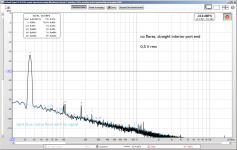
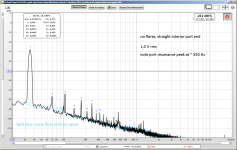
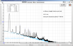
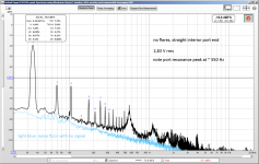

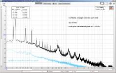
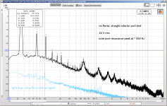
from 1 V on the port resonance is clearly excited; already with 2 V the first harmonic of the port resonance is visible.
generally the noise floor raises; for high levels the noise increases in the lower area and at about 9 kHz.
THD raises gently up to 4 V and then more rapidly. this is mainly due to H2 (and H4) - might be a result of the very unlinear air movement as mentioned in post 24.
by the way: the poor little woofer reaches its xmax at about 8 V rms for frequencies other than 35 Hz!
Nice tests, thanks for reporting it on the forum as well, it's a lot of work!
Looks like you are having great fun! 🙂
Here is the table edited for closed box, for fun 🤓 🤔
I did some experiments with ports some years back, it is critical to minimize noises from it and it's a tough job. It's critical to minimize any box noises for that matter. Then I realized there is no reason to have a port in my application, which is hifi in normal livingroom without strict limit on size or shape and I'm having a DSP anyway so the boost of port isn't really needed. Turns out I have to have a DSP cut even with the closed boxes, where the Helmholz resonance was, due to room modes! good riddance 🙂
This is very good information you and augerpro have provided, many projects benefit from a port!
Looks like you are having great fun! 🙂
Here is the table edited for closed box, for fun 🤓 🤔
| amp output voltage (V rms) | Chuffing audible with sine? | Chuffing audible with low passed music? | Chuffing audible with fullrange music? | SPL dB @ 1m | REW measurement for sine tone noise “N %” | REW measurement for sine THD % | Subjective impression / remark | |
| 2 | no | no | no | 61 | 4,95 * | 0,41 | Sine tone is barely audible! | |
| 4 | no | no | no | 67 | 2,94 * | 0,72 | Sine tone is very silent | |
| 8 | no | no | no | 73 | 1,06 | 1,25 | Sine tone is audible | |
| 11,32 | no | no | no | 76 | 1,04 | 1,75 | ... even more! | |
| 16 | no | no | no | 79 | 1,21 | 2,62 | Nice, it's rocking | |
| 32 | no | no | no | 82 | 1,6 | 6,79 | Music seems to be too loud, impulse to lower the volume instinctively. Smell of voice coil | |
| 64 | no | no | no | 88 | 2,08 | 14,7 | Subjective impression: it’s far too loud, I immediately want to turn it off. This, by the way may partially be due to the small fullrange driver playing near its limit! |
I did some experiments with ports some years back, it is critical to minimize noises from it and it's a tough job. It's critical to minimize any box noises for that matter. Then I realized there is no reason to have a port in my application, which is hifi in normal livingroom without strict limit on size or shape and I'm having a DSP anyway so the boost of port isn't really needed. Turns out I have to have a DSP cut even with the closed boxes, where the Helmholz resonance was, due to room modes! good riddance 🙂
This is very good information you and augerpro have provided, many projects benefit from a port!
Last edited:
Here is the table edited for closed box
🤣
Yes, i have to admit: the more I dig into port behaviour the more I am convinced it's more like a mediocre compromise ...
In other words, I had to do all the work only to realize what several people keep saying since decades.
Hey, but that is great way to learn, I don't know if there is any other 🙂 Doing mistakes that is, try stuff, figure things out.
Because, it's usually not that simple to dismiss or believe something right off the bat. Port might be very good thing on some occasion, while on another it is not necessary. It's good to know what it does and learn when it is good and when it can be leaved out, what's the compromise, where is the trade-off, to know whether to use port in your application.
Besides, I think it is great fun to do it like this, fun time with the hobby, experiment away and find out everything has a trade-off somewhere 🙂 I like to think loudspeaker design is primarily knowing what trade-offs are being taken and its logical not to take any on sound quality if you want to have good sound. If you must have some particular size system or something, then evaluate what the trade-offs are and how significant they are. If they land on audio quality think if the design could be arranged in another way where more trade-offs land on cost or size or something else, somewhere else than on sound quality. Conversely, if it is a budget system then prepare to have some trade-offs in sound quality as well, and that's fine as long as primary goal of the project is met.
Reflex ports are notorious in this respect, simplified to home audio context they trade-off midrange sound quality for more bass, which is silly because more bass can be had just by adding more/bigger boxes to the system, which is actually a good thing for small room sound quality anyway. So, for this reason there is no ports in my system anymore, I took path to add more boxes which increases size and cost and complexity of the system, but hey, that's not audio quality issue so a fine trade-off I can take in my application. It's just matter of saving up and negotiating with the family! Some people want to have easy and small setup without additional bass boxes and ports are fine there, if not mandatory to have any bass. Or what ever the application is, live sound, car sound pressure competition, what ever, know your trade-offs 🙂
Last edited:
not only that but, depending on the port design, also bass can be compromised by chuffing/nonliearities.they trade-off midrange sound quality for more bass
it may still not be noticeable as noise, but it just does not "sound right", it sounds "busy" and "nervous".
Yeah, I've recently started to pay attention on stuff like this, how things are actually perceived and what is their magnitude / importance for good sound quality. What is good sound quality to me in general and how it all changes with playback level, and so on. A lot of it falls into this category "something isn't quite right, but can't quite figure out what it is" which makes this a silly hobby for those who don't like to tinker with stuff for years 😀 So far only conclusion I've arrived is that: minimize all issues 😀
You can make an acoustic rocket ! 🙂Moreover, with longer bass notes there is a constant flow of air starting just outside the center of the port and a return flow from around the port. I suppose for high levels this circular flow can be quite large!
youtu.be/TQ1_B1Wo03s?si=ABr6QRvW-pMW1w_2&t=300
for completeness, here is how i measure responses and spectrum:
response: microphone in front of port, 5 cm distance. low level, about 500 mV
spectrum and distorsion: microphone on the side of the port, 10 cm distance to avoid direct turbulence at the microphone.
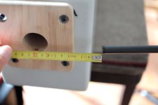
the microphone is connected to an old (but good) focusrite saffire LE firewire soundcard.
i measure responses with REW (and initially with speaker workshop), spectrum and distorsion with REW.
i found perfect settings for the spectrum analyzer in @xrk971 's distorsion measurement thread. thanks!
response: microphone in front of port, 5 cm distance. low level, about 500 mV
spectrum and distorsion: microphone on the side of the port, 10 cm distance to avoid direct turbulence at the microphone.

the microphone is connected to an old (but good) focusrite saffire LE firewire soundcard.
i measure responses with REW (and initially with speaker workshop), spectrum and distorsion with REW.
i found perfect settings for the spectrum analyzer in @xrk971 's distorsion measurement thread. thanks!
Nice work STV!
This is a classical oscillating flow in a pipe problem from a fluid mechanics standpoint. Many technical papers and engineering analyses with non dimensional numbers etc are out there for this problem.
Adding a rounded inlet so that there is not a sharp edge helps a lot but that changes the port length vs a sharp edge one - as the flow resistance drops.
The chuffing is caused by turbulent flow. Transition of laminar flow (quiet) to turbulent in a round pipe is characteristic by the Reynolds number. Try to keep that below 2300 and it should remain quiet.
Re=[momentum forces]/[viscous forces]
= U x D / nu
U = flow velocity in m/s
D = pipe diameter in m
nu = kinematic viscosity or air at room temp
Set D and lookup nu, set Re = 2300 and solve for max U.
Calculate max U from simulation vs audio voltage input. That tells you max signal and SPL before turbulence kicks in.
As an example, let’s take D = 5cm or 0.05m
Kinematic viscosity if air at room temp is about 1.5x10^-5 m^2/sec
Solving for U we get U = Re x nu / D
= 2300 x 1.5E-5 m^2/sec / 0.05 m = 0.7m/sec.
So we need to keep velocity in a 5cm duct below 0.7m/s.
This says that smaller ducts are less susceptible to chuffing. You can add a bundle of straws for example and the characteristic dia is now 0.005m and U is now 7m/sec.
thanks @xrk971 for the competent technical explanation!oscillating flow in a pipe problem from a fluid mechanics standpoint
I still think the most relevant issue is the transition from port to "open space" (or half space), not so much the oscillation in the pipe.
as I personally saw and heard this transition can cause problems at very small sound levels.
and it hugely depends from the port transition design.
I initially wanted to keep this to a later post for creating more suspense - but anyway, here it is:
blowing helmholtz ports are a sign of "port stall"
this is similar to airport stalling (well, less dangerous) because the controlled flow of air is disturbed and turbulences are created, loosing port output.
this is fun to test out (see post #24 and post #34 - thanks @Dmitrij_S !) but it is higly undesirable for good sound, because it creates distorsion, chuffing and a loss of output (compression).
here are two very rudimentary animations that show the principle:
first the bad, ugly, stalling and blowing port:
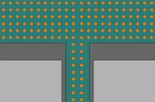
and now the good port:
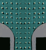
my investigation showed that probably any port will stall at a certain level.
however, the bad port starts stalling (and blowing) at tiny levels.
the good port will only eventually stall at extreme levels.
once more my lousy experiment images:
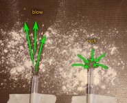
the "natural" flow characteristics of a simple, hard edge tube end shows huge differences for both flow directions.
for a port we need to do everything to keep the flow out from the port and the flow back into the port as similar as possible (thus: consistent sound waves!).
every change of flow characeristic during change of air direction will produce turbulences which create chuffing, distorsion and SPL losses (aka: compression).
I will introduce a spectacular new testing method for port stalling in my next post:
stv's helmholtz port stalling test (c) - "SHePoST"
this will also include fact-based evidence in the form of THD, chuffiing noise and compression measurements.
and some examples of good (and maybe very good?) port designs - not entirely new I must admit 🙂 .
stay tuned!
Last edited:
While speaking of ports ...airport stalling
This should be airplane stalling, of course!
When you say “stall” do you mean the point of flow separation such that there are recirculating zones (eddy’s)? Stall happens on a wing when recirculating flow attaches and breaks the flow and the wing loses lift. The term is not used in pipe flow. Flow in a pipe can choke when it reaches sonic speed at which point, it can flow no faster. That’s not the case here.
Jet exiting a round hole on flat plate is another classic flow that is well studied. The recirculation is not the cause of the chuffing noise but the turbulence in the main core flow itself. It scales with velocity cubed so grows very quickly.
Do a search for “round jet turbulent noise”.
Studies show these types of flows - although not oscillating, do have similar traits.

- Home
- Loudspeakers
- Multi-Way
- Investigating port resonance absorbers and port geometries