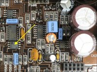
Working on another 500/1, this one shat an audio output section and the power supply is fine. I have removed the audio output FETs and cleaned up the board. Upon application of the remote lead I got no gate drive on the audio outputs, so I replaced the drive IC U500. This brought back drive on all but 1 of the output FETs, Q507 swings positive and stays there till the standby supply shuts off (some seconds after remote lead removal).
I removed and tested all the small transistors in the area:
Q508/509/510/511, all test good.
R506/507/508/509 are within spec.
Anything else that would cause the gate of Q507 to rail like that, even though drive signals out of U500 look good? Seems to me like it's not being pulled back to ground, but not sure where to look next.
Couldn’t really figure anything out trying to trace the source of the problem, so I put the rectifier and outputs back in to see what would happen. Turns out the high side ones are actually the only ones turning on. Soon as rail voltage came up, so did a nice high side drive wave form. I have 76v at the speaker terminals, there’s barely 2v being carried by the low side FETs so apparently I need to figure out why drive has been lost to those instead.
Also when I replaced U500, I noticed R512, R513, R599 and R669 were burnt so I replaced them. Is it possible something else burned up along with those parts?
Also when I replaced U500, I noticed R512, R513, R599 and R669 were burnt so I replaced them. Is it possible something else burned up along with those parts?
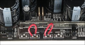
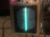
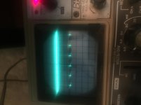
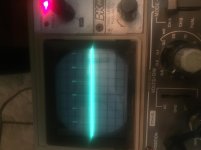
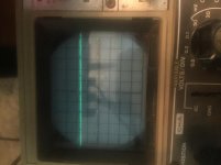
Pins 1/2 on OPAMP shorted, low side FETs jumpered as shown in above post. This is what’s on the gates of Q504/5/6/7 in that order, 10x probe, .5v/div, 10us timebase. Sorry about the crappy quality/rotated shots, I don’t know why that always happens in forums they look fine on the phone. To me it looks like drive is missing from Q504, and the high side FETs have a high duty cycle while the low side have nearly nothing.
Attachments
Last edited:
So I take it this is a PWM duty cycle issue, and not to do with the output stage itself? I can’t extend the board, but I can tack little wires onto whatever point I need and reinstall the preamp board. I assume I’ll be searching for whatever is causing it to drive the high side to full duty cycle even though there’s no input, is this a bad comparator or a railed OPAMP by chance?
- Status
- This old topic is closed. If you want to reopen this topic, contact a moderator using the "Report Post" button.
- Home
- General Interest
- Car Audio
- JL 500/1 (V1) Q507 no gate drive