Hard to explain, but what I’m seeing is:
Duty cycle into the 4427 should be balanced, which should balance the bridge and give equal output voltage to the speaker terminals. Its not balanced, I verified against another amp I have here. One half of the bridge is full on, the other full off. The drive signals I’m seeing bear that out as well, very wide on one side, very narrow on the other.
The clip pot has little effect on the signals, makes them slightly wider at their positive swing but there’s very little range. More than an eighth of an anti clockwise turn, and it flatlines and I get no modulation at all.
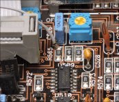
Center the offset and clipping pots.
Desolder the jumper that you bridged the terminals on the op-amp with.
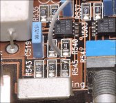
You will need to solder a small wire jumper between two resistors. Use something flexible like ribbon cable. The photos show the resistors.
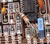
You will need to solder a resistor between terminals 1 and 2 of U513. Soldering to the two resistors connected to those terminals makes it easy. I'd suggest a 10k resistor but anything between 1k and 47k should work.
The offset pot (don't turn it more than about 30° from center) will now drive positive or negative voltage into pin 5 of U503. The output of that op-amp will drive U513. The output of U513 will drive pin 4 of the LM319. That input, compared to pin 5 will drive the pulse width. Confirm at each point.
Desolder the jumper that you bridged the terminals on the op-amp with.
You will need to solder a small wire jumper between two resistors. Use something flexible like ribbon cable. The photos show the resistors.
You will need to solder a resistor between terminals 1 and 2 of U513. Soldering to the two resistors connected to those terminals makes it easy. I'd suggest a 10k resistor but anything between 1k and 47k should work.
The offset pot (don't turn it more than about 30° from center) will now drive positive or negative voltage into pin 5 of U503. The output of that op-amp will drive U513. The output of U513 will drive pin 4 of the LM319. That input, compared to pin 5 will drive the pulse width. Confirm at each point.
Attachments
u503 pin 5 went positive 2vdc for a second, then went negative 2vdc and stayed there as long as power was applied. Pin 4 of the LM319 (there are 2, I assume you mean the one near u513), goes high to +12vdc and stays there, there’s a triangle wave present at pin 5, the output pin 12 is 12vdc with tiny positive and negative spikes riding on it.
Confirm that the offset pot has positive and negative 15v on its outer terminals and that turning it (on the point where you tapped off for the jumper) transitions smoothly above and below 0v as you cross the center rotation of the pot. Take the jumper off for this if it doesn't do as described with the jumper in place.
- Status
- This old topic is closed. If you want to reopen this topic, contact a moderator using the "Report Post" button.
- Home
- General Interest
- Car Audio
- JL 500/1 (V1) Q507 no gate drive