Thanks for the explanation Joe, I think I can figure it out on my own now ")
In the meantime, the enclosure I have been working on is a sealed one.
I had tried a Mass Loaded TL, but it was hard getting it to behave with current drive without any passive filter.
I'll post a quick preview of the dimensions and simulated freq response as soon as I have access to my files later today.
Regards,
Nick
[...]
I use SoundEasy, measure the Z plot and import, then play around with the values that gets the best result. You ideally should end up with a single peak way below Fb. There will be other software equally capable. The only way to demonstrate completely would be a video.
Example Elsinore Mk6:
There are no commercial speakers that gets anywhere close to this kind of result.
Indeed, hard to find something commercial which challenges this graph.
Do you have by any chance the measured SPL plot (standard 1W/1m) with microphone too?
Thanks to all for details, I will look into Qms.
My starting point into this learning experience is that at the end of the day the Qt should be more relevant.
My plans are to use in current mode either: the hard-surrounded/low-excursion pairs of 12" woofers with Qms of 7.5 and 11.5 or the soft-surrounded/long-excursion pair of 10" which has Qms of 3.3. I would not care too much if I burn the 12"#s but our ears loudness problem and the superior acoustical efficiency of 12" around and below 100Hz is a strong argument to try these first. Anyone think or tell from experience that speakers with such "free-air" Qms will be doomed no mater what solutions?
Greetings,
Ionmw
Do you have by any chance the measured SPL plot (standard 1W/1m) with microphone too?
Now I see: the freq. response is taken with a calibrated mic. Impressive.
Cheers,
Ionmw
Example Elsinore Mk6:
This is total (i.e. system) current phase superposition, right? To complete the graph would be necessary to show individual contributions too, e.g. the current phase for each driver. In my opinion, would this be indeed a statement of ultimate system clarity. Or am I wrong?
After taking a look at the Alpair 10.3M and the Alpair's 10P's response in the higher frequencies, I decided to whip up a quick and dirty simulation for the Alpair 10P after all; the 10.3M being already a a bit live up top, the rising impedance of the driver at higher frequencies would have made it a bit too hot. On the other hand, the 10P could looked like it could benefit from a little extra output in the upper octave, expecially when listened to off-axis.
So below is my take on on it.
Bear in mind that this is just a preliminary design can benefit from optimization.
The enclosure details are as follows:
Type: Sealed box enclosure
Length: 400cm
Driver offset from the top: 24cm
Cross sectional area: 3xSd = 264 cm2
The above can be packaged into an enclosure 20cm wide by 40 cm deep and 110cm high, including two internal folds.
The dashed blue traces show the driver's infinite baffle response and behavior while the red traces show the the whole system's behavior.
Planet10 and Joe, your input is appreciated
Attachments
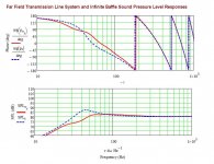
Just a couple of comments about the graphs above:
-3db point is 42hz
-10db point is 24hz
What's also interesting is the fact that the driver's excursion is well controlled by the enclosure.
Let me know if there is any additional data one might want to look at...
Regards,
Nick
-3db point is 42hz
-10db point is 24hz
What's also interesting is the fact that the driver's excursion is well controlled by the enclosure.
Let me know if there is any additional data one might want to look at...
Regards,
Nick
Hi Joe,
I have made only few steps ahead. I tested your circuit in both LTSpice and TinaTi (here using exactly the LM3875 model). I am not 100% through, but till now I can confirm tons of details in this thread, including good operation point, the transconductance mode and linearity (though dependent of R_sense and input voltage, some risk of Xoverdist, other risks if not properly done), etc.
However, I have for you a couple of remarks and questions on some points that I do not understand yet. All are, maybe, not so important for functionality but they are essential for my understanding. If you have time to look again through some posts here would be very kind.
About DC-trim pot:
Indeed simulations do not show any DC-Trim effect, but you experienced a sensitive behavior. What could be the explanation?
About bandpass filter on the input:
Indeed the values of shown schematic produce a strong BP filter, strongly rolling off above 1KHz, phase attention too! What is the purpose for this BP? Why not using a 10uF/4.7ohm set for series RC and obtain a bit of roll-off at 20-30KHz? Moreover, why this BP-filtering matter would be Chip amp dependent, I do not really understand.
Last one for now: you managed a single transformer stereo version. Could you share the schematic too, tune-up details, advises/comments?
Feeds/updates from anyone will be of course appreciated too.
Thanks,
Ionmw
PS. one definition for "current driving"-friendly speakers could be: high-sensitivity with reasonable good Z-flatness or "any HS with QMS reasonably small" (after enclosure)? Right?
I have made only few steps ahead. I tested your circuit in both LTSpice and TinaTi (here using exactly the LM3875 model). I am not 100% through, but till now I can confirm tons of details in this thread, including good operation point, the transconductance mode and linearity (though dependent of R_sense and input voltage, some risk of Xoverdist, other risks if not properly done), etc.
However, I have for you a couple of remarks and questions on some points that I do not understand yet. All are, maybe, not so important for functionality but they are essential for my understanding. If you have time to look again through some posts here would be very kind.
About DC-trim pot:
It must be, since it actually works!
Indeed simulations do not show any DC-Trim effect, but you experienced a sensitive behavior. What could be the explanation?
About bandpass filter on the input:
Would I use this exact circuit? No, as the bandpass filter on the input and the DC trimming may be completely different - so while it is possible to use others, I cannot foresee what needs to be sorted.
Indeed the values of shown schematic produce a strong BP filter, strongly rolling off above 1KHz, phase attention too! What is the purpose for this BP? Why not using a 10uF/4.7ohm set for series RC and obtain a bit of roll-off at 20-30KHz? Moreover, why this BP-filtering matter would be Chip amp dependent, I do not really understand.
Last one for now: you managed a single transformer stereo version. Could you share the schematic too, tune-up details, advises/comments?
Feeds/updates from anyone will be of course appreciated too.
Thanks,
Ionmw
PS. one definition for "current driving"-friendly speakers could be: high-sensitivity with reasonable good Z-flatness or "any HS with QMS reasonably small" (after enclosure)? Right?
Last edited:
About DC-trim pot:
Not sure what you mean, but keep in mind that voltage 'gain' is a function of the load and hence if you have a DC offset, it is twice at 16 Ohm than it is a 8 Ohm, which is twice that of 4 Ohm etc. So something is needed to control that. I adjust the DC first with something like 10R resistor, then increase it to 100R and fine tune it.
About bandpass filter on the input:
Keep in mind that the LM3875 is very popular as a 'Gainclone' chip - about 12 years ago I pointed out that putting a BP on the input had a marked affect on the sound and that it can only be adjusted by the ear. The LP part is clearly limiting max rise time and hence some kind of slewing is going on. I simply copied over the same values I've used before and they seem to work as before. By all means, try different values, but really this should be done by ear only.
Last one for now: you managed a single transformer stereo version. Could you share the schematic too, tune-up details, advises/comments?
The use of one transformer I would not recommend as this circuit is very prone to hum. Hence my schematic was also drawn as a wiring diagram as well (wire it exactly like that and you won't induce hum). To be honest, I can't remember all the details except it was very difficult to do with a single transformer and keep it hum free. I only built this amp because I wanted to demonstrate to disbelievers that the Elsinore speakers could be driven by a current/transconductance amplifier. Then thought, why not share it? So I did.
My comment about current driving friendly speakers I think was about the Elsinores, commercial loudspeakers should not be used. But if you mean fullrange driver, then low inductance and low Qms is fairly desirable.
Cheers, Joe
The use of one transformer I would not recommend as this circuit is very prone to hum.
Do note that if you are good, 1 xfmer can be made to work. The variable transconducance amp the we (Daniel aka Duo) built (a slighly more complicated version of Joe's version) was built with 1 power xfmer and a modified ChipAmp/AudioSector LM3875 circuit board. No Hum. A very nice amp.
I believe that Daniel started a thread on this amp. It predates Joe's but did not gain much traction.
dave
Hi Joe,
thanks for useful details and thoughts.
DC-zero: meanwhile I observed that the TinaTi model of LM3875 needs best a 1K series with 500 trimpot. The 10K trimpot was way too-sensitive (for simulation parameters).
Low inductance(!?) wow... to flatten Z at trebles... means deep performance sacrifices and good above-average engineering to not loosing everything. This, yet again, speaks for full range drivers, where lowZ is a must to have compromise on many more counts.
But then again the old argumentative dance "current vs. voltage": take any Low-Z and low-QMS driver, do some adjustment of Bass and Trebles, and it will behave identically (SPL wise) regardless of voltage or current. Differences would be, I guess more likely, only in some clarity (pro for current) or some simplicity (pro for voltage).
My take is that you prove, exemplary well, that much of current world advantages are available with same weight and not too complicated setup by using standard solid state. For selected few of custom made drivers and enclosures - who can sound clearer -, a simple current amp ought to be seriously considered.
Cheers,
Ionmw
PS. Here the first goal is to check if some "cheap" (500Eur) standard drivers sound clearer and better (current) compared to a really good CL730 + Graetz HSA200 vintage pair (voltage). The second goal is to custom make a loudspeaker+amp setup which sounds in semi-field as clear and tight like... Sennheiser HD450 as start. You would think... is possible?
thanks for useful details and thoughts.
DC-zero: meanwhile I observed that the TinaTi model of LM3875 needs best a 1K series with 500 trimpot. The 10K trimpot was way too-sensitive (for simulation parameters).
I guess with 1,5uF/4.7Kohm (see attachment) you compensate Z increase at trebles to obtain linear power vs. freq. for a given fullrange driver, much like an active pre-Xover? Also, the slewing argument makes sense for full range driver.Keep in mind that the LM3875 is very popular as a 'Gainclone' chip - about 12 years ago I pointed out that putting a BP on the input had a marked affect on the sound and that it can only be adjusted by the ear. The LP part is clearly limiting max rise time and hence some kind of slewing is going on. I simply copied over the same values I've used before and they seem to work as before. By all means, try different values, but really this should be done by ear only.
My comment about current driving friendly speakers I think was about the Elsinores, commercial loudspeakers should not be used. But if you mean fullrange driver, then low inductance and low Qms is fairly desirable.
Cheers, Joe
Low inductance(!?) wow... to flatten Z at trebles... means deep performance sacrifices and good above-average engineering to not loosing everything. This, yet again, speaks for full range drivers, where lowZ is a must to have compromise on many more counts.
But then again the old argumentative dance "current vs. voltage": take any Low-Z and low-QMS driver, do some adjustment of Bass and Trebles, and it will behave identically (SPL wise) regardless of voltage or current. Differences would be, I guess more likely, only in some clarity (pro for current) or some simplicity (pro for voltage).
My take is that you prove, exemplary well, that much of current world advantages are available with same weight and not too complicated setup by using standard solid state. For selected few of custom made drivers and enclosures - who can sound clearer -, a simple current amp ought to be seriously considered.
Cheers,
Ionmw
PS. Here the first goal is to check if some "cheap" (500Eur) standard drivers sound clearer and better (current) compared to a really good CL730 + Graetz HSA200 vintage pair (voltage). The second goal is to custom make a loudspeaker+amp setup which sounds in semi-field as clear and tight like... Sennheiser HD450 as start. You would think... is possible?
Attachments
Last edited:
Thanks Planet10, but how good? If you want tell me please, I genuinely appreciate simplicity at higher levels (system). Apparently I am not good enough, so my approach is taking course on 0.5kVA T1 with 12x power voltage controllers: stereo * tri amp-ed * symmetric PS. Yes, of course active buffered Xover-s too: to align the custom marriage of driver+enclosure. It makes sense, as Joe's did, as we all do.Do note that if you are good, 1 xfmer can be made to work.
Why variable TIA? Does no-hum come from this variable transconductance? A link?The variable transconducance amp [...] No Hum. A very nice amp. I believe that Daniel started a thread on this amp.
Greetings,
Ionmw
Last edited:
Why variable TIA? Does no-hum come from this variable transconductance? A link?
Different loudspeakers prefer a different output impedance. Daniel's goes from near zero to near infinite. His 1st one was a repurposing of an amplifier he built to drive an electron tube.
No hum because he is good.
http://www.diyaudio.com/forums/solid-state/165130-curious-extra-knob-trans-amp.html
dave
Do note that if you are good, 1 xfmer can be made to work... a slighly more complicated version of Joe's version
Yes indeed, but I basically wanted it so simple that I wouldn't get blowback on how to fix problems and also the original simplicity of the Gainclone amp guided me, to make as it inviting for many to do. This was classic KISS DIY.
I believe that Daniel started a thread on this amp. It predates Joe's but did not gain much traction.
Sound like it deserved to. I have seen the thread, is there s schematic, as I was looking for it? Yes, familiar with Rod Elliott's stuff here in Sydney. He and I have spoken.
Hi Joe,
I need help. Have you seen any influence of the sense resistor value into the audio quality? Because I intend to use +/-24V/1A regulators and assuming that I still see the 32ohm W-driver resonance then I need to change R_sense from 0.3ohm to 1ohm. Assume a correct DC-trim null adjustment.
Aside from this, I feel reserved to put 2 or 3 amps (at nominal 0.7V input) into a standard driver with current source; likely 1.1A @ resonance would be more electrically sound, limiting total power at about 10W (this is acceptable to me, meaning 106dB SPL into a small room). But I am curious: Do full-ranges fare better with these currents like 2-3A - I mean through all their resonances ? You mentioned early low-Le and low_Qms, to me this is indicative of low number of turns and heavier wires (among some more other details): so in principle I expect you answer this question with a yes, but I feel better if I double check.
Thanks,
Ionmw
Last edited:
My kind request to clarify the matter still needs to be picked up. I hope you (schematic ChipAmp/AudioSector LM3875) and Joe (schematic 2x xfmer) will consider as appropriate to do this. Meanwhile I solved my problems. When ready and tested I will make them public. Thanks. beginning was better though.Do note that if you are good, 1 xfmer can be made to work.
Kind of understand. From my perspective it did not attract me on any counts. I shall refrain from further public comments, as they could be misread as criticism, but in fact I express only my opinion. I need a solution that do not have some ultra-dangerous "magic buttons". Why: I still have kids at home, and wife and friends etc and I do not want to stand police in front of "magic button": no one touch this! I hope that you, others too, will understand what I mean. In contrast, Joe's post is at least simple enough to prove (and partially explain) a very efficient method. Of course if any of us will make only this simple schematic... then I only hope they do it for testing only then dismantle, as Joe did. The final solution , the "to stay" one, must necessarily be more complex.The variable transconducance amp the we (Daniel aka Duo) built (a slighly more complicated version of Joe's version) was built with 1 power xfmer and a modified ChipAmp/AudioSector LM3875 circuit board. No Hum. A very nice amp.
I believe that Daniel started a thread on this amp. It predates Joe's but did not gain much traction.
dave
Now, back to your web site: those paint dots on your modified speakers are very smart, bold though. Cute looking too. Technically well I do not estimate a gigantic effect, but it's a good direction. I wish you can improve it. And the re-coating of cones, too. The conformal coating that you use I guess is a Urethane spray. I will test.
BTW which do you estimate as contributing more to make those drives better: the paint dots or the additional coating? Care for any percentage wise, type of paint used? My estimate is... well up to 3% total improvement, depending how heavy is the paint (60% Ag-filled, my first guess). Right?
Really: any FEM simulations for contributions of paint dots?
Cheers.
Ionmw
PS: meantime I have read on "Rasmunssen effect"...; VERY SAD what happened there. It is a normal FILTER, interacting with a "black box" DAC chip (imperfect). So... what, the product and system managers (aka. usually "the smarter" colleagues of DAC components engineers) did a lousy job, as usual, and killed a potentially better DAC. Nothing new. But... "Effect [name]" title not deserved... technically speaking. Really, did you Joe have had to be so... persistent? There are some other very good specialists here too... It is almost insulting us all... to call it "effect". You could say "finding", "point" , "lesson" whatever... And for 3rd time: it is a FILTER, check any school manual, or any books whatever advanced level.
Last edited:
those paint dots on your modified speakers are smart though. Well I do not estimate a gigantic effect, but it's a good direction. Keep up. And the re-coating of cones too.
BTW which do you estimate as contributing more to make those drives better: the paint dots or the additional coating?
No one knows yet why it works, but it does. Differences cn be significant if the source provides the information. The spots (and the accompanying conformal coating) provide the more significant improvements. Other steps taken on some drivers aim to work on resonance issues that a driver might have.
dave
Nothing new. But... "Effect [name]" title not deserved... technically speaking. Really, did you Joe have had to be so... persistent?
Only want to brief or off topic. I didn't name it, somebody else did and yes, there is something 'new' because it has a switch-like effect on the DAC that is totally explainable and not a filter 'effect', a way to measure this this odd behavour is now seriously being sought. If that can be produced as data, then it just can't be argued - and will point to what is really happening.
Now back on topic. Many have eyed the relatively inexpensive Usher S520 speakers:
An externally hosted image should be here but it was not working when we last tested it.
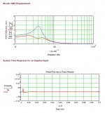
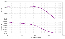
I have developed a new Crossover for this little speaker that means to can be driven by a transconductance/current amplifier, and I am thinking about posting it as DIY project. I am very pleased by the result so far. It's only a change in Crossover plus a small addition of acoustic damping materiel added internally. The old Crossover is removed and the drivers are wired straight to the existing terminals on the back (four) and the new Crossover is external and four wires connects it.
The impedance plot and current phase angle plots below.
Attachments
My first guess is that the local combined effects of mass-load plus your 2-long-spots choice geometry are more effective in damping resonances. The larger the cone-diameter you put them on, the lower the frequency modes affected. A good theoretical example is given in Fostex NF1 Application Note. I thought you found your inspiration there, since you modify so many Fostex-s. According to them the Trebles MUST be confined only around the dust-cap (or Phase Plug). The MIDs should not extend to the sicken. etc. To me it seems correct. Though a FEM simulation would prove it better, I agree on this too.No one knows yet why it works...
What do you mean?Differences cn be significant if the source provides the information.
Right. I am ultra CURIOUS how they soundThe spots (and the accompanying conformal coating) provide the more significant improvements. Other steps taken on some drivers aim to work on resonance issues that a driver might have.
dave
Sadly you located too far.Ionmw
A good theoretical example is given in Fostex NF1 Application Note. I thought you found your inspiration there, since you modify so many Fostex-s.
Althou i had read the NF-1 AppNote when the speaker was released, the EnABL modis all Bud Purvine, and pre-dates the NF-1 by a considerable margin.
What do you mean?
EnABL shows its stuff by allowing the speaker to reproduce lower level information (ie the speaker has greater DDR). When i am participating in a blind test, for instance, i use the ability to throw a much better 3D image to quickly pick the EnABLed drivers. That information has to be in the software before that is possible.
I am ultra CURIOUS how they sound
There are pairs of these drivers in Germany & the whole of Europe so travel to Canada is not necessary.
dave
- Home
- Amplifiers
- Chip Amps
- Joe Rasmussen "Trans-Amp" - 40 Watt Transconductance "Current Amplifier"