I have been a little slow getting back to things today. We flooded overnight and have been busy getting someone to pump out the basement. Give me a chance to look over what was said overnight. Can I E-mail you at the address in your profile?
Steve, take as long as you want. Seeing as how it took me over two weeks to respond to this, I've got no room to talk. I hope your basement thing gets taken care of soon, and that the maggies and other items are okay.
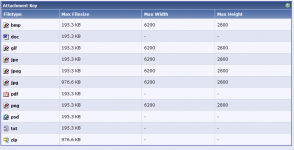
It's fine to email me. I just looked at the file size limit for the forum, and it's 976k for zip files. I would think that a schematic would be smaller than this, but if you have a problem posting it, don't hesitate to email.
Last edited:
Hi Thomas,
The HiFi is fine. The basement floor isn't completely flat and the stereo is at the high end. It was only about an inch of water in the low spots. I am sitting in my chair, but my feet are wet. The shop is fine. It doesn't have a basement.
Andy,
I guess I haven't tried to post a large file since the upgrade. Wasn't the old limit 100k? I will make a PDF and post it.
I started reading from where I left off yesterday. Can someone tell me where some of my posts went? And why? I had quoted GK in a post that is now gone. I also see that his post was changed after I quoted from it. Are there new rules I should know about? I certainly didn't say anything that should have been objectionable.
The omnipresent Net Nanny

I actually edited that post about 2 or 3 minutes before your reply appeared (while you were typing). It was a remark on the comments of others intent on resurrecting this 'debate'. I deleted it because I figured it would be taken personally.
Referring back to my question in post 77,
http://www.diyaudio.com/forums/solid-state/151295-krill-next-generation-4.html#post1965615
I am not trying to insult GK with my question. Perhaps I am misunderstanding what is being said by either GK or Andy. It seems that Andy is saying the circuit will only operate as I think at high frequencies and GK is saying it can only work at low frequencies. Since these appear to be opposing views, I simply ask which is correct. I could be interpreting on of you incorrectly. Is that the case?
As a follow up to my previous question, here is what my simulator says. This was run on the amp that I started this thread with and is the one I will be posting the schematic for later. The first 3 are at rated output of 50W into 8 ohms. This is the minimum current in each emitter resistor at the listed frequencies. You can see how this could lead me to believe the outputs stay on. These numbers lead me to believe GK might be correct at some sufficiently high frequency, but it should be well outside the audio band.
8.87827M amps Minimum at 20 KHz
9.98479M amps Minimum at 1K Hz
10.0355M amps Minimum at 20 Hz
9.99978M amps at DC with 28.3VDC at output with 8 ohm load
8.87827M amps Minimum at 20 KHz
9.98479M amps Minimum at 1K Hz
10.0355M amps Minimum at 20 Hz
9.99978M amps at DC with 28.3VDC at output with 8 ohm load
Hmm. The data I was looking at are in your post #4 of this thread. This shows 96uV across a 0.22 Ohm emitter resistor, giving 436 uA per device.
Quoting myself from post 4:
You will notice that this amp is of the inverting persuasion. There is no reason for this other than this was what I was working on at the time I decided to do this. I used 0R22 emitter resistors and 34V supplies. I should also state that this amp uses 4 pair of output transistors. Again, it is what I was working on.
I think "working on" is the key here. I changed a few values as I worked on the design. I now feel it is finished. Attached is a Zip file with the schematic in PDF. The node numbers didn't print for some reason. They do show in the print preview. I am also including a screen shot of the schematic which does show the node numbers. I have also included the net list of the complete amp. It will very interesting to see how the results differ between sim packages.
I checked out the Intusoft demo package. The 20 component limit does make it pretty useless.
I just tried to attach the Zip file and was told it exceeds the limit. I will try breaking into 3 files.
Okay, let's backtrack a bit. The detailed simulation data you presented were contained in posts 4 through 14. Those are the data I'm trying to correlate. Then in post #39, you included the netlist. Is it correct to say that the netlist of post #39 is from the same simulation used to create the graphs in your posts that were between 4 and 14?
No, it is not safe to say that. The first netlist I posted for you did not include the complete amp. I was trying to keep the component count down for the demo version. I didn't realise at the time that only 20 components were allowed. I had stated back in post 27:
You should have everything you need in the files I posted today. Now everybody has the same information if they use those files. I promise I wont change anything now that I feel the design is finished.
I threw everything out and started over. Fortunately, parts are cheap in simulation. I even changed the brand of some of the transistors, so these numbers won't be exactly the same as the previous amp.
You should have everything you need in the files I posted today. Now everybody has the same information if they use those files. I promise I wont change anything now that I feel the design is finished.
Referring back to my question in post 77,
http://www.diyaudio.com/forums/solid-state/151295-krill-next-generation-4.html#post1965615
I am not trying to insult GK with my question. Perhaps I am misunderstanding what is being said by either GK or Andy. It seems that Andy is saying the circuit will only operate as I think at high frequencies and GK is saying it can only work at low frequencies. Since these appear to be opposing views, I simply ask which is correct. I could be interpreting on of you incorrectly. Is that the case?
We're talking about 2 different things here.
1) With a cap between the bases of the drivers, it is only at low frequencies (depending on the cap size) that a "dynamic" biasing circuit could maintain non-switching of the output devices. At higher frequencies a large cap ensures that the biasing voltage is pretty much fixed.
2) At high enough frequencies, without a bias resistor for the drivers of the double EF, the power output devices may not have enough time to fully turn off.
Last edited:
Steve,
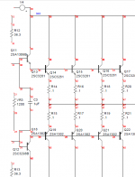
The PDF you posted, "50W DIY Amp Scxreen Shot .pdf" is missing a bunch of the circuitry, making it impossible to associate all the node numbers on the schematic with those of the netlist. See the capture below. The front end came out fine, but the front end is not really part of the discussion about data correlation at this point. The circuitry in between the front end and the output stage - shown on the left side of the diagram below - is missing.
The PDF you posted, "50W DIY Amp Scxreen Shot .pdf" is missing a bunch of the circuitry, making it impossible to associate all the node numbers on the schematic with those of the netlist. See the capture below. The front end came out fine, but the front end is not really part of the discussion about data correlation at this point. The circuitry in between the front end and the output stage - shown on the left side of the diagram below - is missing.
Attachments
Last edited:
No, it is not safe to say that. The first netlist I posted for you did not include the complete amp.
I think it's preferable not to look at the complete amp for the purpose of correlating simulation results. Since the discussion thus far has centered on the behavior of the output stage anyway, adding the input stage doesn't really clarify anything. It just muddies the waters further, making it more difficult to construct a working simulation file from the netlist. For example, suppose you aren't able to post a legible schematic containing node numbers corresponding to the netlist. From the one you posted above, it looks like there's some technical difficulties in the capture that are causing garbled schematics. If these difficulties can't be overcome, I could generate the simulation from a netlist of just the output stage - without the schematic. If you still have the full simulation files corresponding to the original netlist you posted in post #39, that may be the simplest way around all this. Do you still have them? It shouldn't matter that the netlist isn't for the final design. In fact, the discussion on output stage behavior was about your already existing design anyway, not some as yet undetermined future design.
Last edited:
Andy,
I am attaching the screen shot with node numbers again. This time it looks to be complete. I posted the complete amp because that is what I thought most here (as DIYers) would want to see. This is not some some "as yet undetermined future design". This is still the same basic amp, both VGS and OPS, that I presented originally. It has been changed slightly for improved low impedance performance and drive so it can be used in a bridged design for 200W output at 8 ohms. That is the reason it is an inverting amp. This has been built by me in the past, and is a working product. I have taken advantage of the sim program I have now, but not then, to adjust some component values. I do still have the files from post 39. What exactly would you like me to do with them? Lets keep it clean here!
I am attaching the screen shot with node numbers again. This time it looks to be complete. I posted the complete amp because that is what I thought most here (as DIYers) would want to see. This is not some some "as yet undetermined future design". This is still the same basic amp, both VGS and OPS, that I presented originally. It has been changed slightly for improved low impedance performance and drive so it can be used in a bridged design for 200W output at 8 ohms. That is the reason it is an inverting amp. This has been built by me in the past, and is a working product. I have taken advantage of the sim program I have now, but not then, to adjust some component values. I do still have the files from post 39. What exactly would you like me to do with them?
Lets keep it clean here!- Status
- This old topic is closed. If you want to reopen this topic, contact a moderator using the "Report Post" button.
- Home
- Amplifiers
- Solid State
- Krill - The Next Generation