Hi Jens,
-Chris
I need better test equipment to do this reliably. Maybe it is enviroment since I am using an RTX.If they can't measure the distortion at -140dB they need better test equipment...
-Chris
That makes sense, it would mean they solved the problem.My approach would be one of the new 20bit "R2R" DAC's with a de-glitcher and maybe an error correction cycle. I think one of these could approach -130dB so divided down as a lock in signal there should be no problem.
The nicer AP test sets provide two generators, the DAC generator, and the "High Performance Sine Generator" which is analog, and not able to be locked to anything. My old version 555 High Performance Generator has a distortion floor at the sweet spot at 2kHz of -154dBc for 2nd, and -159dBc for 3rd. On the newer APx-555 (type B) with the improved generator, I measured -150dBc for 2nd and -159dBc for 3rd at 2kHz.
So, a DAC generator is indeed synchronous by design, but for low residual tests, nobody uses them because they are at least 20dB worse than a high quality Wein bridge oscillator.
AP does provide a synchronous analyzer function which will trigger the start of an FFT capture buffer based on the zero crossing of the generator waveform, but it's not actually synchronous, and it does not address the skew between generator frequency and FFT analyzer sample clock.
Similarly, while I'm not aware of it, if AP offers a "use band center" option, it merely alters the numeric input to the oscillator so that the entered number is one of the actual FFT band center frequencies. This assumes that the analog oscillator is accurate and non-drifty, something that the newer 555 type B oscillator is supposedly capable of, but again, it is not a synchronous oscillator at all. I too choose my band centers for tests by looking at the available options from an FFT display, and choose a frequency where not only the fundamental falls in a band center, but also the 2nd, 3rd and 4th harmonics are also exact band centers - you can do that by hand inspecting the FFT bin centers and using a calculator to check harmonics. In some higher frequency ranges though, my oscillator's harmonics are off one or two bands with a 512K point transform, so again, this is not a cure-all, especially with the older 555 oscillator which is not as frequency accurate as the 555 type B oscillator.
A synchronous Wein bridge oscillator really is a different animal. I think it will probably come down to implementation details but it will be interesting to see whether a VCO or an injection locked oscillator will be able to control a Wein bridge oscillator without ruining the residual.
If they can't measure the distortion at -140dB they need better test equipment...
Send an email to Bruno
AP (the older 2722) offers an option to software shift the acquired data to bin centers. So it does not change the oscillator but re-samples the data to fall in the center of bins.
That means it also works with an external oscillator like Victors. In fact, it is specifically meant for external oscillator use. AP calls it 'open loop' measurement.
Jan
That means it also works with an external oscillator like Victors. In fact, it is specifically meant for external oscillator use. AP calls it 'open loop' measurement.
Jan
A synchronous Wein bridge oscillator really is a different animal. I think it will probably come down to implementation details but it will be interesting to see whether a VCO or an injection locked oscillator will be able to control a Wein bridge oscillator without ruining the residual.
That wasn't my suggestion. I was trying to describe an oscillator good enough to use as an injection lock for the Wein bridge oscillator.
@Jan have tried the injection of a very small amount at the control point like that app note.
The nicer AP test sets provide two generators, the DAC generator, and the "High Performance Sine Generator" which is analog, and not able to be locked to anything. My old version 555 High Performance Generator has a distortion floor at the sweet spot at 2kHz of -154dBc for 2nd, and -159dBc for 3rd. On the newer APx-555 (type B) with the improved generator, I measured -150dBc for 2nd and -159dBc for 3rd at 2kHz.
So, a DAC generator is indeed synchronous by design, but for low residual tests, nobody uses them because they are at least 20dB worse than a high quality Wein bridge oscillator.
AP does provide a synchronous analyzer function which will trigger the start of an FFT capture buffer based on the zero crossing of the generator waveform, but it's not actually synchronous, and it does not address the skew between generator frequency and FFT analyzer sample clock.
Similarly, while I'm not aware of it, if AP offers a "use band center" option, it merely alters the numeric input to the oscillator so that the entered number is one of the actual FFT band center frequencies. This assumes that the analog oscillator is accurate and non-drifty, something that the newer 555 type B oscillator is supposedly capable of, but again, it is not a synchronous oscillator at all. I too choose my band centers for tests by looking at the available options from an FFT display, and choose a frequency where not only the fundamental falls in a band center, but also the 2nd, 3rd and 4th harmonics are also exact band centers - you can do that by hand inspecting the FFT bin centers and using a calculator to check harmonics. In some higher frequency ranges though, my oscillator's harmonics are off one or two bands with a 512K point transform, so again, this is not a cure-all, especially with the older 555 oscillator which is not as frequency accurate as the 555 type B oscillator.
A synchronous Wein bridge oscillator really is a different animal. I think it will probably come down to implementation details but it will be interesting to see whether a VCO or an injection locked oscillator will be able to control a Wein bridge oscillator without ruining the residual.
These are good points, but I suggest we do not rule out a state variable oscillator as the choice. Victor's Wein bridge oscillator is truly amazing, especially given its relative simplicity, but I suspect that an SVO can be made with equal performance given the same care that Victor put into his entire design. I do not buy that just because a SVO has 3 op amps instead of just one that it must have more distortion.
Cheers,
Bob
That wasn't my suggestion. I was trying to describe an oscillator good enough to use as an injection lock for the Wein bridge oscillator.
@Jan have tried the injection of a very small amount at the control point like that app note.
Aaaah. That's a good plan. With an AP analyzer, that makes synchronous everything easy - just use the DAC generator to lock an external injectable oscillator and there's nothing else special that needs to be done.
Sorry for the confusion.
These are good points, but I suggest we do not rule out a state variable oscillator as the choice. Victor's Wein bridge oscillator is truly amazing, especially given its relative simplicity, but I suspect that an SVO can be made with equal performance given the same care that Victor put into his entire design. I do not buy that just because a SVO has 3 op amps instead of just one that it must have more distortion.
Indeed. Two of the amplifiers in a SVO are usually integrators, so they will have maximal feedback and should be very clean. Good point.
Indeed. Two of the amplifiers in a SVO are usually integrators, so they will have maximal feedback and should be very clean. Good point.
Also, the two integrators can be in series after the summing op amp (where agc distortion and noise are injected) so that one gets a 12-dB/octave post-filtering effect after that point if the output signal is taken from the second integrator.
The fact that quadrature versions of the signal are readily available makes possible the implementation of a 4-phase agc detector, providing less ripple and at a higher 4X ripple frequency. A crazy person could even make an 8-phase rectifier by combining quadrature signals to get 45-degree signals for additional rectification.
Tweak-tuning JFETs as part of a tuning network across the integrator resistors could be referenced to ground by connecting their sources to the virtual grounds of the integrator op amp inverting inputs. But there are other ways to tweak-tune the SVO that might even be better. For example, a single JFET could tweak-tune the gain of the summer (whose gain is often nominally unity). This latter approach gets any tuning JFET distortion injection behind both integrators, just as for the agc circuit.
Cheers,
Bob
Hi Jens,
I need better test equipment to do this reliably. Maybe it is enviroment since I am using an RTX.
-Chris
Send an email to Bruno
Of course a notch filter is required to get to that level.
The Mola Mola does seem to have a very good performance. I just felt that the "not measurable (estimated -140dB)" was a bit strange, when we are dealing with lower distortion oscillators in this thread, which I believe can be measured with a notch filter + a good ADC. On my own version of the low distortion oscillator I have measured -153dB THD at 1 kHz.
Without the notch filter the RTX6001 only goes to around -130 to -133dB THD at optimum levels (at 1 kHz).
Please how does the "shift to bin center" feature actually work? At what points is the resampling ratio calculated, how often is it updated? How is the incoming frequency measured to determine the current ratio? Are long FFTs still effective with this setup?
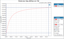
A 1M FFT at 48kHz takes 20 secs to gather 1M samples, while having bin of 0.048Hz. Does a freewheeling analog oscillator stay stable within 0.048Hz for 20s, or is the incoming signal split into short chunks and the resampling ratio changes/gets updated very often, many times within single FFT run?
Thanks for explaining.
From the AP manual:
The frequency correction technique has a maximum correction range of ±4%. At the low end of the frequency range there will be frequencies that are more than 4% from a bin center. For example, with a 16,384-sample transform and 48 kHz rate, 37 Hz is approximately the lower limit above which a sine wave at any arbitrary frequency can be guaranteed to be brought to a synchronous frequency.
The technique will work at still lower frequencies if the signal frequency is within 4% of a synchronous bin center frequency. Bin center frequencies may be computed from the equation
Frequency = (N * Sample Rate)/TransformLength ; where N is the integer number of cycles in the transform.
For example, with N = 7 (exactly seven complete cycles in the FFT buffer), a transform length of 16,384 and a 48 kHz rate, the synchronous frequency is 20.5078125 Hz. A ±4% range around that frequency extends from approximately 19.7 Hz to 21.3 Hz, and a sine wave within that range will be corrected to the synchronous frequency.
This is the section discussing the lower limit for the re-sampling. It seems it does this for the whole transform buffer, but of course it assumes that the frequency remains constant during the acquisition.
Jan
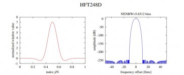
In my Linear Audio article I referenced a paper with some new flat top windows with extremely low spectral leakage. In the end it's the spectral leakage that defeats the ability to average out the noise, if you think about it the spectral leakage is energy from the measured frequency not the noise, flat top windows sacrifice frequency resolution for lower sidebands.
Here's an example. You don't care about the exact frequency but are only interested in averaging out random noise. This window has -248dB leakage and the input oscillator only needs to be +- 0.5 bin over the measurement period so averaging of a series of time records should achieve the desired effect. I'm a little strapped for time but I could run a simulation of this.
This is trivial to put into Matlab or any other similar program.
This is trivial to put into Matlab or any other similar program.
Attachments
jan: It seems to me that feature is for analyzing stable frequencies which just do not fit the power-of-2 FFT bins. Perhaps integer-only frequencies? I wonder how the frequency is measured initially.
Modern algorithms and computing power allow any FFT length, no reason to be limited to 2^n lengths. FFT at 48k length takes just a few ms on any current CPU.
FFTing frequency-unstable incoming signal is a very interesting problem.
It would be nice if these legacy devices with great analog and DAC/ADC performance could be hooked to current computers with modern software processing. I would be surprised if no such projects existed.
This window has -248dB leakage and the input oscillator only needs to be +- 0.5 bin over the measurement period so averaging of a series of time records should achieve the desired effect.
That is very useful, but will an analog oscillator stay within +/-0.5 bin for longer FFT time (hence smaller bin)?
That is very useful, but will an analog oscillator stay within +/-0.5 bin for longer FFT time (hence smaller bin)?
The point is you don't need absolute frequency resolution to measure the THD. There is a tradeoff between longer FFT's and more short FFT's averaged. There is no free lunch, flat top windows have a wider equivalent noise BW i.e. more averages.
At least there is presented a complete answer that we could run with, the authors note that HP and SRC offer proprietary windows HP even going to the length of requiring an NDA. This is the way it should be open source.
This needs some test exercises.
- Home
- Design & Build
- Equipment & Tools
- Low-distortion Audio-range Oscillator