Actually with that special flat-top window no resampling would be required, that's very useful indeed.
Yes, I see problems with SRC at the -250dB level. This window is an extreme example, -160dB would probably cover any practical problem. Also the +-0.5 bin number is for very accurate amplitude resolution, much more drift would still have minimal issues. I have some time tomorrow, I might try some numerical simulations.
The bottom line is the need for approximately 25X the sample periods, but the process is very straight forward and easily implemented in many tools.
Instantaneous frequency can be extracted from a record of the oscillator signal, but this means that Fourier analysis would then have to be performed off-line.
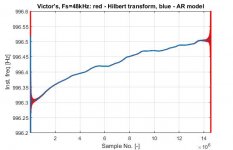
I'm enclosing a diagram of the instantaneous frequency in a record of the Victor oscillator's output during a 5-minute period, sampled at a rate of 48kHz.
Two methods have been used: the Hilbert transform followed by phase unwrapping (red line), and by means of an assumed autoregressive (AR) model generating the oscillator output signal.
The second method is rather involved so I'm not going to go into detail here. I developed it almost 20 years ago for a different purpose, the details are in a paper I wrote several years ago.
Both methods require the oscillator signal to be bandpass filtered around the fundamental frequency before being used for the extraction of the inst. freq., for the result obtained is otherwise very noisy.
The utility of the inst. freq. info would be to find an optimal bin width for the subsequent FFT.
Regards,
Braca
Attachments
Instantaneous frequency can be extracted from a record of the oscillator signal, but this means that Fourier analysis would then have to be performed off-line.
I'm enclosing a diagram of the instantaneous frequency in a record of the Victor oscillator's output during a 5-minute period, sampled at a rate of 48kHz.
This looks similar to the results we got trying to extract the instantaneous frequency from a test LP. The Hilbert transform uses FFT's so it is circular and hence there is no avoiding the discontinuity as it wraps around and you get Gibbs ringing. For the most part the techniques give the same answer.

Instantaneous frequency can be extracted from a record of the oscillator signal, but this means that Fourier analysis would then have to be performed off-line.
I use estimating single- or dual-sine frequency with least-squares curve fitting (nonlinear regression). Only several periods of samples are required for very precise results and noise/random measurement errors are automatically averaged out due to the nature of the LSM. Can be run at any part of the signal since the regression finds best-fitting frequency, amplitude, and phase at once.
Fitting with default params takes tens of ms in interpreted octave (loops involved), and less in java/julia using pre-compiled libraries (native, C)
Yes, the LSQ method method is definitely much faster than the parametric spectral estimation method I used for the blue line in my attachment.
On the other hand, the latter needs only a few consecutive data samples to determine the inst. freq. In this particular case I used eight data samples to obtain a single frequency value, but it would have worked with less.
This approach was developed for an application where this resolution was needed, and is certainly an overkill in this case.
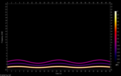
Jan: Perhaps the AP feature could be tested with a signal designed to emulate the oscillator frequency fluctuation, while being artificially pre-distorted to known value (well above DAC/ADC internal levels). My reasoning is if the analyzer measures the distortion correctly (relative to the fundamental), it is re-calculating the samplerate continuously to avoid the distortion "smear".
Since all bins have equal width, if the fundamental falls into 2 bins during the measurement => H2 falls into 4 bins, H3 into 6 bins, changing their relative FFT amplitude accordingly.
A simple octave generator is at generate_fluct_sine.m * GitHub , the fluctuation is much stronger to see the effect on the spectrum. Any param can be changed as required when generating the wav file.
Attachments
Would you consider running it in online octave instead, so that you can play with the documented params as much as you like? Changing the params is trivial for you. Honestly, I would prefer this method of self-enablement ")
Octave Online * Cloud IDE compatible with MATLAB -> register with anything, copy the octave script to the editor in the middle, run, push reload button in the file browser on the left to see the created flac, download, use. Works perfectly, just tested the same.
E.g. YouTube
Octave Online * Cloud IDE compatible with MATLAB -> register with anything, copy the octave script to the editor in the middle, run, push reload button in the file browser on the left to see the created flac, download, use. Works perfectly, just tested the same.
E.g. YouTube
Sorry this is not possible. Every DAC on earth has more THD than a well designed analog oscillator.
That's profoundly wrong.
DACs are always better than the ADCs of the same technology.
The phase accumulator that feeds the DAC can easily produce the digital
equivalent of the "right" harmonics in amplitude and phase shift and
subtract them from the digital signal that goes to the DAC.
You even can tune out the imperfections of the ADC. The analog signal
that goes to the DUT does not need to be wonderful. It's enough to
be quite OK and to know the error.
Even if you think you have an ultra clean oscillator, you cannot be sure
about that. It could well be the case that you have just compensated the
errors of your FFT analyzer.
cheers, Gerhard
(who did work on mixed signal wafer testers)
The phase accumulator that feeds the DAC can easily produce the digital
equivalent of the "right" harmonics in amplitude and phase shift and
subtract them from the digital signal that goes to the DAC.
Do you have any practical experience with that? You mention both the DAC and ADC, experience with both?
...you cannot be sure about that. It could well be the case that you have just compensated the errors of your FFT analyzer.
It's possible to tell very precisely what the situation is, with just a bit of effort.
That's profoundly wrong.
DACs are always better than the ADCs of the same technology.
The phase accumulator that feeds the DAC can easily produce the digital
equivalent of the "right" harmonics in amplitude and phase shift and
subtract them from the digital signal that goes to the DAC.
While this seems plausible for sine wave signals, how does this extrapolate to complex waveforms like music? What does it mean to make a "harmonic" of dense program material and subtract it away to cancel distortion?
In reality, it's all sine waves. Only more.
That's right. The set of all continuous functions forms a vector space. The sine function and all its harmonics are an orthogonal set of vectors that span the space. Meaning any arbitrary vector (continuous function) can be represented as a linear combination of the spacing set.
I think (without going back and reading, and I haven't been reading that closely) they're just talking about linearizing a slightly nonlinear DAC, and doing that with a sine wave output is just adding harmonics of the same level and opposite polarity to how they appear in the DAC output with a pure digital sine input. This correction isn't meant for, and won't work for music, it's only for a sine wave or other static/repetitive waveform.While this seems plausible for sine wave signals, how does this extrapolate to complex waveforms like music? What does it mean to make a "harmonic" of dense program material and subtract it away to cancel distortion?
However, presuming I'm reading it right, this could be done with a lookup table (generating a sawtooth wave and adjusting the table so a perfect sawtooth is at the output), and this would make an overall "more nearly perfect DAC" whether it's a sine or any complex and changing waveform.
Thinking this through, for a 24-bit DAC, this would be a 2^24 or 16.7 million+ input table with 24 bits (3 bytes) per entry, or a 50 megabyte+ table. It would also take a while to figure out what values to put in the table, though that's just a "simple matter of engineering."
Hmm. Maybe I should patent that or at least copyright it as a Creative Commons thing, presuming no one else has thought about it. That's a biggish lookup table, but well within current technology. Surely someone has thought of this before.
I originally thought the question was the "how do you get a complex musical waveform vs. a sine wave in digital audio?" question, which should really be a separate thread (it's already been discussed in several threads), but this website/book answers it:
The Scientist and Engineer's Guide to Digital Signal Processing
Click on "Browse and/or download chapters from the book" to begin reading.
Last edited:
that's nice.
i would, too.
mlloyd1
i would, too.
mlloyd1
Hi All,
There was an earlier comment about making David's low distortion oscillator board available. It is okay with his widow. She thinks it would be really cool to see his creation being made, and I agree. I'll build one for sure if we get boards for it.
-Chris
- Home
- Design & Build
- Equipment & Tools
- Low-distortion Audio-range Oscillator