When the test frequency is a synchronous subharmonic of the DDS clock, the sine table
collapses to a pretty short list since most values are never needed. Nowadays it could be
done in software - with a DMA transferring the list repeatedly to the DAC.
I believe that it's important that the test frequency be an exact synchronous subharmonic of the DDS clock. Otherwise there are spurious beat-note products generated that are akin to high-order IM between the DDS clock and the test frequency being synthesized. They would of course have very low amplitude set by DAC resolution, but I believe they wouldn't be tolerable in this high purity objective.
Last edited:
yes, and one would not need a window function when everything falls naturally
into the middle of the bins. At least for the fundamental and the first harmonics.
For high harmonics and IMD it may be hard to find suitable frequency ratios.
But then, for the dwarf signals we do not need excellent sidelobe suppression,
so a simple window will do.
into the middle of the bins. At least for the fundamental and the first harmonics.
For high harmonics and IMD it may be hard to find suitable frequency ratios.
But then, for the dwarf signals we do not need excellent sidelobe suppression,
so a simple window will do.
Last edited:
here are some pictures of the Davada oscillator
https://www.diyaudio.com/forums/equ...n-audio-range-oscillator-191.html#post4943639
https://www.diyaudio.com/forums/equ...n-audio-range-oscillator-191.html#post4943639
the user interface, or at least one version of it. #5106
Low-distortion Audio-range Oscillator
and some measurements with 725, #5120, #5121, #5125, #5128
Low-distortion Audio-range Oscillator
and some measurements with 725, #5120, #5121, #5125, #5128
Last edited:
Just build 8-th order LPF, than any decent oscillator with -100dBc THD would have -148dBc. All it costs 8 high quality OPA.
Yes, I have also proposed this approach and did some preliminary tests for proof of concept. Worked well.
I have also tried a tunable, high Q, notch filter to remove a particular harmonic.
I prefer to have a single source which does -148 without the extra tuning of filters or notches to do.
However, if you have a source already at -148, it can be dropped further to -160 or less with LPF or notch.
-RNM
Last edited:
Yes, sure I can make a photo of it. Yes, i paid david to build it for me. No, I dont want or need to get money for it back. Water under the bridge. I wanted it and at same time help david get some money and pcb layout done, So he could sell the pcb's for DIYers.
We need to find his pcb layout art work on his computer.
-Richard
That's good Richard, wondering is all, since you brought up financials.
Water under the bridge = sunk cost.
")
Board layout, art work:
That might have to come from anatek, as he's helping David's widow
sort through things.
So if he made boards up, the information should be on the board.
His widow supply board house with legal docs for manufacturing it,
she can assign them to someone to handle the manufacturing and distribution
etc and receive a royalty from it also.
I know that Davada was thinking along those lines of DIYboards, etc
because we discussed it briefly.
Cheers,
here are some pictures of the Davada oscillator
https://www.diyaudio.com/forums/equ...n-audio-range-oscillator-191.html#post4943639
Well that didn't work well at all. It took me back here:
the user interface, or at least one version of it. #5106
Low-distortion Audio-range Oscillator
and some measurements with 725, #5120, #5121, #5125, #5128
Which didn't work well either as it also took me back here.
Now, If I can link to these posts before editing times out, I'll do here:
#5106 with 725 measurement: #5120, #5121, #5125, #5128
Last edited:
The links still don't work. however the numbers do. In the default settings it would start around page 511. I believe Richazard has the software and I might also somewhere. Still the source code would be nice. I think the layout ans schematic are in Diptrace. Anyone have experience with Diptrace?
Just build 8-th order LPF, than any decent oscillator with -100dBc THD would have -148dBc. All it costs 8 high quality OPA.
Wouldn't that LPF not add its own distortion?
Jan
The links still don't work. however the numbers do.
When I tested them, clicking on the post number (which are links that I made)
do work. Is that what you were referring to? The numbers are the links.
Cheers,
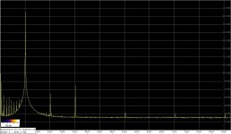
As a proof of concept, I made a test with a single-stage LP filter at the output of a simple, lamp-stabilized Wien bridge oscillator.
Since the passband ripple is of no consequence, one can trade the ripple for the filter steepness, so I used the Chebyshev topology with a passband ripple of 3dB. The simulation gives me an attenuation of approx. 14dB at the 2nd, and 21db at the 3rd harmonic.
The filter was realized in the MFB topology, with polystyrene capacitors and normal quality resistors.
I did this in another forum, and I'm repeating the results here for convenience.
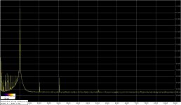
The first spectrum shows the oscillator harmonics in the as-is version, and on the second one (LP filter in) the 2nd is lower by 14dB, and the 3rd by 17dB. Although it seems that the filter potential of 21db attenuation at the 3rd has not been fully realized, it is also the level where the THD of my audio interface comes into play.
Note that the right part of the fundamental freq. skirt in the spectrum is less wide with filter.
The op-amp used for the measurements shown was OPA627. However, I also used the Groner/Polak composite op-amp in the filter (thanks for the adapter PCB, Jan), but the results did not change.
Regards,
Braca
Since the passband ripple is of no consequence, one can trade the ripple for the filter steepness, so I used the Chebyshev topology with a passband ripple of 3dB. The simulation gives me an attenuation of approx. 14dB at the 2nd, and 21db at the 3rd harmonic.
The filter was realized in the MFB topology, with polystyrene capacitors and normal quality resistors.
I did this in another forum, and I'm repeating the results here for convenience.
The first spectrum shows the oscillator harmonics in the as-is version, and on the second one (LP filter in) the 2nd is lower by 14dB, and the 3rd by 17dB. Although it seems that the filter potential of 21db attenuation at the 3rd has not been fully realized, it is also the level where the THD of my audio interface comes into play.
Note that the right part of the fundamental freq. skirt in the spectrum is less wide with filter.
The op-amp used for the measurements shown was OPA627. However, I also used the Groner/Polak composite op-amp in the filter (thanks for the adapter PCB, Jan
), but the results did not change.Regards,
Braca
Attachments
diyaudio links contain both post ID and thread page.
Default posts count per page is 10. Those links assume 50 posts on page. That number is configurable in User CP - Number of Posts to Show Per Page.
I used to have 50 posts configured too, but reverted back to defaults for this very reason.
Default posts count per page is 10. Those links assume 50 posts on page. That number is configurable in User CP - Number of Posts to Show Per Page.
I used to have 50 posts configured too, but reverted back to defaults for this very reason.
Here is David's osc at 10KHz .. 1.5KHz is better


THx-RNMarsh
View attachment dlbSVO V5 SCH Sheet 1.pdf
View attachment dlbSVO V5 SCH Sheet 2.pdf
View attachment dlbSVO V5 SCH Sheet 3.pdf
View attachment dlbSVO V5 SCH Sheet 4.pdf
THx-RNMarsh
View attachment dlbSVO V5 SCH Sheet 1.pdf
View attachment dlbSVO V5 SCH Sheet 2.pdf
View attachment dlbSVO V5 SCH Sheet 3.pdf
View attachment dlbSVO V5 SCH Sheet 4.pdf
Last edited:
Wouldn't that LPF not add its own distortion?
Jan
Filters composed of opamps with a C in nfb will attenuate the harmonics from LPF.
THx-RNMarsh
Well, this whole thread is about generating single harmonic tone.
 Crazy, isn't it? You can see what people are capable of.
Filters composed of opamps with a C in nfb will attenuate the harmonics from LPF.
THx-RNMarsh
-120dB attenuated 6dB per octave 2nd is still only -126dB. Your perspective would be different if you had experience with this.
Google 'peaking distortion in higher order filters' or similar.
Jan
Depends on topology. I build a Sallen-Key 6-th order and discovered that my filter instead of attenuation thd-3 down, in reality kicking its up to about +30 dB. Long troubleshooting with pots, capacitors type and re-ordering of stages turns blank, till I discoveredWouldn't that LPF not add its own distortion?
Jan
"Harmonic Distortion in a Class of
Linear Active Filter Networks
PETER J. BILLAM
Filtek A.G., Biel, Switzerland
Journal of the Audio Engineering Society, June 1978, Volume 26 Number 6, pp.426-429".
I want my filter to be variable, and seems state variable (SVF) has huge advantage over any other having two network elements with zero common mode, perfect place to put CMOS analog switches. Continue experimenting.
- Home
- Design & Build
- Equipment & Tools
- Low-distortion Audio-range Oscillator