I have the board populated correctly, soldered and now testing.
9v transformer ac in (more like 10.5 measured) and trying to get 5v dc out...
The 'L' pad is bridged and the others open but the lowest I can dial down with the variable resistor is 5.42v dc out.
Does not vary from no-load to lightly loaded.
Same result (5.51v on the other) for each side of the dual board used as separate supplies.
Do I lower the 3k3 at the 'L' point, reduce the ac input voltage, change the .1R resistor to .2R or higher or something else ?
Your guidance will be most welcome.")
-Bob
9v transformer ac in (more like 10.5 measured) and trying to get 5v dc out...
The 'L' pad is bridged and the others open but the lowest I can dial down with the variable resistor is 5.42v dc out.
Does not vary from no-load to lightly loaded.
Same result (5.51v on the other) for each side of the dual board used as separate supplies.
Do I lower the 3k3 at the 'L' point, reduce the ac input voltage, change the .1R resistor to .2R or higher or something else ?
Your guidance will be most welcome.
-Bob
Last edited:
Hi Bob
Just bridge the 'M' pad as well. Keep the AC voltage as it is.
The 0.1R is a current limiting resistor. Increasing it to 0.2R will lower the point at which it limits, from 6A to about 3A, which might not be a bad thing since something would fry before 6A was reached.
John
Just bridge the 'M' pad as well. Keep the AC voltage as it is.
The 0.1R is a current limiting resistor. Increasing it to 0.2R will lower the point at which it limits, from 6A to about 3A, which might not be a bad thing since something would fry before 6A was reached.
John
Last edited:
Excellent ! Thanks John. The bridging of 'M' got it down to 5.03v which I am more than happy with.
I also changed the current limiting resistor to 0.2R and may even go to 0.4R as I have several .2R I could series... oh the joy of ratting out old boards for parts...
I'm going to use the supplies to power an Xmos usb board and a SRC feeding into an ESS 9028 dac board.
I also changed the current limiting resistor to 0.2R and may even go to 0.4R as I have several .2R I could series... oh the joy of ratting out old boards for parts...
I'm going to use the supplies to power an Xmos usb board and a SRC feeding into an ESS 9028 dac board.
Last edited:
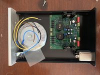
Just got some bits from Audiophonics including their Studer board. Stock current limiting resistors on my board are 0.1r. Got an 80VA 2x12v transformer, hopefully no issue there. Test fit photo attached.
Board is bigger than Audiophonics say: 118x101mm (NOT 117x95). Approx 45mm total height too (not 42).
Board is bigger than Audiophonics say: 118x101mm (NOT 117x95). Approx 45mm total height too (not 42).
Attachments
Last edited:
Got an 80VA 2x12v transformer, hopefully no issue there.
What output voltage and current do you want?
Is it dead ?
Hi, I recently bought a ready-built Studer900 clone power supply from eBay and have just connected it up for the first time. I have a 20-0-20 traffo connected to the front of the p/s and a NAC152 clone preamp connected to the DC side. I'm building an amplifier for my son but am not an electronic engineer and have some, but limited experience with this sort of thing.
On power-up I was reading 22V DC from both sides of the supply but over a period of a few minutes (I was thinking/hoping it might stabilise somewhere around that voltage) the voltage ramped up to 36V and seemed to stabilise around that level. My preamp needs dual 24V. Am I likely to have killed it with 36V ? I do hope not !
The AC voltage measured as 19V as compared with about 21V no load. Is that drop normal-ish or a cause for concern ?
I am at a bit of a loss how to proceed with diagnostics. Any help or insight that anyone could offer would be very much welcome.
Thanks,
Bo
Hi Bo
I assume you have a dual supply board, so it needs input from two separate 0-20V windings. How have you connected your 20-0-20 traffo? You can't get 36V out from 20V AC so I think you must have been putting 40V in to the board.
Your preamp won't like 36V unless it has overvoltage protection.
I assume you have a dual supply board, so it needs input from two separate 0-20V windings. How have you connected your 20-0-20 traffo? You can't get 36V out from 20V AC so I think you must have been putting 40V in to the board.
Your preamp won't like 36V unless it has overvoltage protection.
Hi, I recently bought a ready-built Studer900 clone power supply from eBay and have just connected it up for the first time. I have a 20-0-20 traffo connected to the front of the p/s and a NAC152 clone preamp connected to the DC side. I'm building an amplifier for my son but am not an electronic engineer and have some, but limited experience with this sort of thing.
On power-up I was reading 22V DC from both sides of the supply but over a period of a few minutes (I was thinking/hoping it might stabilise somewhere around that voltage) the voltage ramped up to 36V and seemed to stabilise around that level. My preamp needs dual 24V. Am I likely to have killed it with 36V ? I do hope not !
The AC voltage measured as 19V as compared with about 21V no load. Is that drop normal-ish or a cause for concern ?
I am at a bit of a loss how to proceed with diagnostics. Any help or insight that anyone could offer would be very much welcome.
Thanks,
Bo
I agree with jonners that it is electrically impossible to get +/-36 VDC from 20-0-20 AC windings. It is either a defective transformer or incorrect connection. What is the 2 rails of the DC volt after the rectifier and the DC out from the board after it ramp up?Hi Bo
I assume you have a dual supply board, so it needs input from two separate 0-20V windings. How have you connected your 20-0-20 traffo? You can't get 36V out from 20V AC so I think you must have been putting 40V in to the board.
Your preamp won't like 36V unless it has overvoltage protection.
We may be able to help more if you show the winding diagram and your connection.
Last edited:
Hi Bo
I assume you have a dual supply board, so it needs input from two separate 0-20V windings. How have you connected your 20-0-20 traffo? You can't get 36V out from 20V AC so I think you must have been putting 40V in to the board.
Your preamp won't like 36V unless it has overvoltage protection.
Hi Jonners, thanks for your response.
Yes I have a dual supply board. The traffo secondary has 3 wires, two outer wires at 30VAC and a centre wire as ground. I connected the outer wires to the outside connector of each power supply input and the centre wire to the inside connector of one input, with a short link wire to the inside connector on the other side. This seemed logical to me.
I tested the traffo before I connected it up and I got about 21VAC between the centre wire and each of the outer wires, so if I was supplying 40V to the board, which is absolutely the logical conclusion, I don't understand how I did it. That conclusion, furthermore, is bolstered by the fact that, having removed the board and given it a visual inspection all around, it is evident that the top of each smoothing capacitor is bulging and the plastic jacket on one of them has split, presumably preparatory to venting itself. Worrying stuff.
What are the chances that if I replace the smoothing capacitors and sort out the supply voltage issue (assuming that is what it is) the rest of the board will be OK ? Would I need to replace all the other electrolytics, for example ?
Thanks, again, for your support.
Bo
Hi Keilau, thanks for helping out.
I'll try to attach some images to illustrate the situation.
Hope that clarifies what I've got connected and how I've connected it up.
Thanks again.
Bo
I'll try to attach some images to illustrate the situation.
An externally hosted image should be here but it was not working when we last tested it.
An externally hosted image should be here but it was not working when we last tested it.
Hope that clarifies what I've got connected and how I've connected it up.
Thanks again.
Bo
Hi Keilau, thanks for helping out.
I'll try to attach some images to illustrate the situation.
An externally hosted image should be here but it was not working when we last tested it.
An externally hosted image should be here but it was not working when we last tested it.
Hope that clarifies what I've got connected and how I've connected it up.
Thanks again.
Bo
OK, let me just try that again:
An externally hosted image should be here but it was not working when we last tested it.
An externally hosted image should be here but it was not working when we last tested it.
Here's hoping...
Bo
Hi Bo
The schematic of this board is difficult to follow, but it is designed for two separate outputs which can be connected at the output end to create a dual supply. If the input windings are not completely separate from each other I don't know what would happen, but it does look like the main smoothing capacitors have had their rating exceeded.
I looked up an eBay description of the board, and it says "Input Voltage Range: Dual 9V-24V (4 line transformer)." I think that's the issue.
Hi, I have varying output voltage from my Studer900, worked well for 4 months then this started. Contacted seller on F/Bay, MiniSnow but they would not send a replacement. (DO NOT USE SELLER MiniSnow)
So when I connect the trans the Studer (should be 18 VDC) will output voltages ranging from 8 VDC to 22 VDC. Have tried 3 different trans into this unit & results the same.
Can anyone give me an idea of what may be malfunctioning. Nothing is getting hot.
Thanks for any help
Is this a single or dual board, and what exactly are the input and desired output voltages?
- Home
- Amplifiers
- Power Supplies
- low noise Pre-Amp / DAC power supply MJE15034 TL072 Regulator based on STUDER 900