George,Sorry for not responding so far.
Hans and Lucky, thank you for your interest, particularly for the sim efforts.
Hans, don’t spend your time again trying to chase stupidity.
I had connected both pre channels at the generator out, L directly, R in series with the Shure cartridge for to monitor L out and R out on the scope simultaneously and when the time came for measurements, I forgot to disconnect L from the generator.
So, the input impedance did change and the diagrams in post # 487 were (unintentionally) misleading.
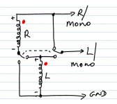
I attach the schematic of what I have built and the connection used to take the measurements (only one channel connected this time)
Lucky, I am going to take measurements with an R in place of the cartridge
George
Are you sure the 1nF is in place between opamp 1 and 2.
Even with 100Mhz GBW opamps I can't get the steep deviation above 100Khz.
I'm anxious to see the results with no Cart, just the 50 Ohm generator and the 420 Ohm.
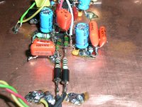
Looking at your pictures in #470, the input resistors that I can see are 200 Ohm (Red, Black, Black, Black) in series with 22 Ohm (Red, Red, Black, Gold), totalling only to 222 Ohm instead of 420 Ohm ???
Hans
Series wiring is best IMO, and works very well IME.Hey everyone, What is the best way to utilize one of(all?) of these TI circuits for mono playback? Strap a stereo cart at the headshell? a simple summing switch in the pre? Parallel or Series? Hope I havn't started something crazy :-/
Attached is a schematic for how to wire bottom of tonearm as switchable between mono/stereo, for the SE version, without re-wiring the headshell.
Another one missing after the purge, presumably.
For Auraks, switching doesn't quite work prefectly because the small series resistor is slightly wrong for one case. But errors and small, and one can choose to optimise for mono or stereo.
Ground only applies to the SE version.
LD
Attachments
Are you sure the 1nF is in place between opamp 1 and 2.
Yes, it is in place, physically and functionally.
But I have not used IC1 bypass capacitor C14 (22pF) and IC2 bypass capacitor C15 (10pF). The only RF filter is a ferrite bead at the input lead of the series input resistor .
That resistor that you read as 22 Ohm was actually 220K (red, red, black, orange) and it made the IC1 to attenuate instead of amplifying (!!).Looking at your pictures in #470, the input resistors that I can see are 200 Ohm (Red, Black, Black, Black) in series with 22 Ohm (Red, Red, Black, Gold), totalling only to 222 Ohm instead of 420 Ohm ???
I have changed it from the beginning to a proper 220 Ohm. So in total they are 200+220=420 Ohm
I'm anxious to see the results with no Cart, just the 50 Ohm generator and the 420 Ohm.
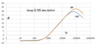
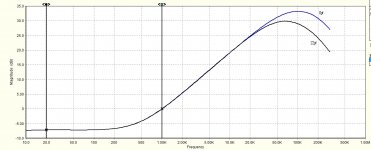
Results with a short in place of the cart (plus the series 420 Ohm resistor) are shown in black in the second attachment.
Only in this case, I had to shunt the 50 Ohm generator with 50 Ohm to reduce the 0.01Vpp (the lowest level my generator was switching to) by 6dB because the preamplifier was overloading at some frequencies. Therefore the 50 Ohm shunt, turns the 50 Ohm generator into a 25 Ohm generator.
If you haven't already, would you please do a run with just a resistor equal to the cartridge coil resitance, so we can see the transfer function of your new Aurak ?!
Results with a 1342 Ohm resistor in place of the cart ( plus the series 420 Ohm resistor) are shown in green.
George
Attachments
Thank you George.Results with a 1342 Ohm resistor in place of the cart ( plus the series 420 Ohm resistor) are shown in green.
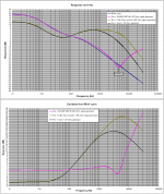
All is mostly working as it should with your SE Aurak. Except that it behaves as if you have fitted the 22pf Miller C on the 1st stage op-amp, whereas you posted that you haven't. This doesn't affect the audioband, but affects ultrasonics as shown in simulations below.
Attached is a plot of your real measurement versus sim (0pf), and also a sim of Miller C 22pf versus 0pf.
This could be because of layout strays, or perhaps because of op-amp GBW being lower than its supposed to be. Sims assume 10Mhz.
I think this is worth bottoming out if we are going to analyse ultrasonics, but in practice for listening to the audioband it will be fine anyways.
PS: The equation you've sketched on your schematic to calculate series resistor, for your variant based on x3 cart inductance should be R = 3L-Rc, rather than 3L-2Rc as you've written. But 420R is the right value anyway!
LD
Attachments
I'm almost sure the 420 Ohm is still in place as being part of the Preamp.Thank you George.
All is mostly working as it should with your SE Aurak. Except that it behaves as if you have fitted the 22pf Miller C on the 1st stage op-amp, whereas you posted that you haven't. This doesn't affect the audioband, but affects ultrasonics as shown in simulations below.
Attached is a plot of your real measurement versus sim (0pf), and also a sim of Miller C 22pf versus 0pf.
This could be because of layout strays, or perhaps because of op-amp GBW being lower than its supposed to be. Sims assume 10Mhz.
I think this is worth bottoming out if we are going to analyse ultrasonics, but in practice for listening to the audioband it will be fine anyways.
PS: The equation you've sketched on your schematic to calculate series resistor, for your variant based on x3 cart inductance should be R = 3L-Rc, rather than 3L-2Rc as you've written. But 420R is the right value anyway!
LD
So you should add 50 +1342 + 420.
Then you will get the same curve as George.
Hans

George, I wonder why you don't use an anti Riaa network behind your 50 Ohm sine wave generator.
Results are much faster to obtain and probably more accurate.
Here is an proposal for a circuit.
Accuracy is within 0.1dB up to 100Khz and -1dB at 300Khz.
Output impedance is 5 Ohm, so it will hardly interfere with the Aural design.
Hans

Results are much faster to obtain and probably more accurate.
Here is an proposal for a circuit.
Accuracy is within 0.1dB up to 100Khz and -1dB at 300Khz.
Output impedance is 5 Ohm, so it will hardly interfere with the Aural design.
Hans
Hi Hans, when there is no coil inductance, just a resistor, the resistor value only affects overall gain, of course. So in simulating George's test with just a resistor I obtain similar shape results to George whether 1395R or 1815R is used, except for gain, and except for the ultrasound region as posted. So I normalised simulation results to 0dB@1kHz, as George has, for easy comparison.I'm almost sure the 420 Ohm is still in place as being part of the Preamp.
So you should add 50 +1342 + 420.
Then you will get the same curve as George.
Hans
LD
This is a good idea !George, I wonder why you don't use an anti Riaa network behind your 50 Ohm sine wave generator.
Results are much faster to obtain and probably more accurate.
Here is an proposal for a circuit.
Accuracy is within 0.1dB up to 100Khz and -1dB at 300Khz.
Output impedance is 5 Ohm, so it will hardly interfere with the Aural design.
Hans
View attachment 609937
LD
Hi Hans, when there is no coil inductance, just a resistor, the resistor value only affects overall gain, of course. So in simulating George's test with just a resistor I obtain similar shape results to George whether 1395R or 1815R is used, except for gain, and except for the ultrasound region as posted. So I normalised simulation results to 0dB@1kHz, as George has, for easy comparison.
LD
Hi LD, did you use the LF412 with the very low GBW of 4Mhz.
It's is a very bad amp for this position, but as you can seen in my sim above, all 3 curves are adjusted at 0dB@1Khz, and the resistor only curves do correspond with Georges recordings.
Hans
No, and I agree that explains it. When I use a 4MHz GBW model, I obtain the same result as you and George.Hi LD, did you use the LF412 with the very low GBW of 4Mhz.
LD

Afraid I'm lost.......With the model used in #507 to achieve the +2dB shoulder left of the dip, Lcart being split in 2 parts of (200mH//5k + 388mH) in series with Rcart = 1342 Ohm, FR with the internal generator would look like below.
Hans
View attachment 609960
George has built the SE version of Aurak, so splitting coil impedance and treating each half differently isn't really an option for modelling reality, I think?
What we know now is the transfer characteristic of the SE Aurak George has, from the result of testing with just a resistor. Although it would seem good to confirm with a reverse RIAA network test, we shouldnow expect the real result to be very close to the simulation, ie near ideal, at least for the audioband ?
I think 3 next steps spring to mind: 1) reverse RIAA network tests to confirm result in George's test setup a) with cartridge b) with resistor; 2) playback f sweep of audioband using test record; and 3) listen to a record and see if the cartridge actually tolerates TI loading (!)
LD
In George's posting #503 you can see a 2dB increase between 10Khz and 20Khz.Afraid I'm lost.......
I called this part the "shoulder" left of the dip at 44Khz.
The only way to achieve such a "shoulder" is to split Lcart in 2 parts and place a resistor in parallel to one of the two parts.
In this case I have divided the 588mH in (200mH//5k + 388mH) giving me exact what I tried to achieve, a 2dB " increase in FR between 10Khz and 20Khz.
The dip at 44Khz was simmed by placing 2 caps and one resistor.
Al my simulations were performed with the SE Aurak version, exactly to every detail to George's version.
When simulating the internal generator, the caps causing the dip are no longer playing a role for known reasons, but the split Lcart in 2 parts with the resistor will stay as they were before with the external generator.
As you have made clear yourself, there is a distinct difference between external and internal generators.What we know now is the transfer characteristic of the SE Aurak George has, from the result of testing with just a resistor. Although it would seem good to confirm with a reverse RIAA network test, we shouldnow expect the real result to be very close to the simulation, ie near ideal, at least for the audioband ?
For the internal generator the parasitic caps causing the dip are not longer playing a role, resulting in two different FR's for external and internal generator
Good planI think 3 next steps spring to mind: 1) reverse RIAA network tests to confirm result in George's test setup a) with cartridge b) with resistor; 2) playback f sweep of audioband using test record; and 3) listen to a record and see if the cartridge actually tolerates TI loading (!)
Hans
Hi dear co responders
I see you are working hard on this.
Hans thanks for the reverse RIAA filter suggestion. I’ll try to build one.
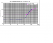
I did a series of voltage measurements of the generator’s output in open circuit and then, when connected to the circuit. Using the voltage divider formula I calculated the input resistance of this version of Aurak3 I have built. See attachment.
I think I have to remove the ferrite bead from the pre input and repeat the measurements.
The OPA2134 will arrive soon for to replace the LF142.
George
I see you are working hard on this.
Hans thanks for the reverse RIAA filter suggestion. I’ll try to build one.
I did a series of voltage measurements of the generator’s output in open circuit and then, when connected to the circuit. Using the voltage divider formula I calculated the input resistance of this version of Aurak3 I have built. See attachment.
I think I have to remove the ferrite bead from the pre input and repeat the measurements.
The OPA2134 will arrive soon for to replace the LF142.
George
Attachments
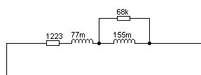
Attached is the Rod Elliot model for cartridge self-inductance. We have possibly found the self inductance of the M97, which we did suspect and certainly why I was keen for George to do his measurements.
Or something else...
Hi Bill,
This is 100% the same as what I did, only the values are different.
Hans

- Home
- Source & Line
- Analogue Source
- mechanical resonance in MMs