Hans: Thank you.
Brinkman: as a balanced/differential setup is a special form of a specialised MM stage not sure a new layout is needed for that IF the twisted pair boards work. But a single ended board that will work well for the hobbyist would be handy. Probably needs a seperate thread at that point for all the debate on through hole vs SM and NE5534 vs everything else arguments that run and run")
Brinkman: as a balanced/differential setup is a special form of a specialised MM stage not sure a new layout is needed for that IF the twisted pair boards work. But a single ended board that will work well for the hobbyist would be handy. Probably needs a seperate thread at that point for all the debate on through hole vs SM and NE5534 vs everything else arguments that run and run
On trust that this is the case, and despite it, for whatever reason the esd rating seems somewhat sensitive in the scheme of things. But at least now we know that, and can take care with cartridge grounding for the practical purpose of prototypes. And we now are informed about the risks and how to mitigate them if we choose, and each make our own decisions.The protection with 4 diodes to the power rails you are referring to are already part of the OPA1632.
Bill, AFAIK, the reason some designs use external ESD rail clamps when there are internal diodes, is to protect the internal protection diodes (!)
For purpose of prototyping the balanced 1632 version, personally I'll take good care with cartridge grounding, take care when connecting/disconecting, and otherwise rely on internal protection diodes. Then swear profoundly when changing SMT op-amps
LD
I have the Happ paper I was posting about, Happ, L. R. (1979). "Dynamic Modeling and Analysis of a Phonograph Stylus." J. Audio Eng. Soc 27(1/2): 3-12.Sounds plausible but I can't recall seeing any MC FR plots that show the dip so I would need some convincing.
There are many possible choices as to the modeling technique used to represent a mechanical system. The traditional method within phonocartridge development has been the electrical/mechanical analog circuit. The approach taken in this study was to mathematically describe the stylus system in terms of a series of continuous, flexible beams undergoing transverse vibrations. It is assumed that the structure undergoes sinusoidal motion and thus the wave equation for the beam has a general solution. The boundary conditions are progressively improved to provide a realistic representation of the system. New approaches to stylus shank design are presented.
Whilst I don't agree with all of it, especially the boundary conditions which define modes of vibration available, I think by happy coincidence the general form of the model is good, and it is well worth seeking out on the web and reading IMO.
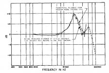
Part of the paper describes the transfer function of the cantilever system in isolation, and compares modelled versus real measurements of f response. In this, the real measurement shows a classic mid-dip, whereas the model doesn't (my thesis is because the model excludes tonearm effective mass element).
Attached is the relevant plot.
There is no clear trend from the Miller Audio data, which is a pity because that is the only site I know with such comprehensive test measurements.
My thesis predicts that mid dip would be more pronounced in carts with low compliance, and therefore low damping, typically identifiable by low VTF requirements. I believe this might be why MCs tend to show it less, if that is the case at all, perhaps ? I'd cite some of the old Shure carts a an example, I think ?
One might ask 'what's a few dB of mid shape between friends?', but I believe it probably has a mechanical cantilever cause, rather than a generator artefact as commonly accepted. So thought this a good place to trot it out......
LD
Attachments
Last edited:
Ooops yes, I mean high compliance of course !Don't you mean high compliance?
I'm a spring constant, rather than compliance, sort of thinker.........
LD
Ooops yes, I mean high compliance of course !
I'm a spring constant, rather than compliance, sort of thinker.........
LD
The kickstarter turntable I've been playing with has a very low mass tone arm does that explain the greater presence dip in my plot? I'm a little frustrated right now by the fact that changing to a Denon is outside of all its adjustment ranges.
I'm a little frustrated right now by the fact that changing to a Denon is outside of all its adjustment ranges.
Hi Scott
Which Denon?
When I fitted the DL-103 on the SME3009 II Improved (a light but not very light arm), I added weight at the headshell (*).
Conequently I had to add mass at the counterweight and the bias weight. I used plasteline (ease of use, works also as a damping element)
(*) Apart from the numerous anecdotal internet opinions that DL-103 sounds better with added mass, I did it while monitoring the waveshape when reading the highest modulation velocity 300Hz track of HFN test record. It tracked it exemplary with 2.5g tracking weight. Note that the user manual allows 2.8g for heavy modulated material
George
Attachments
So far as I know no boards done by anyone .Hans and LD,
Thanks, So the #346 schema is the one I could breadboard and use different op amps? Looks good, will there be any boards done for that one??
Hans
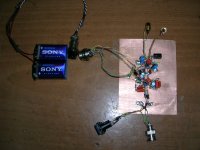
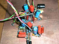
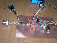
I spent the day building the Single ended Aurak V3 trimmed for the Shure M97xE.
IC1 LF412, IC2 NE5532.
I’ll fire it up tomorrow after rechecking connections. Wish me good luck
Left channel input is signal generator only.
Right channel input is signal generator in series with the M97
I’ ve ordered some OPA2134 for IC1. I’ll have them in a week.
George
IC1 LF412, IC2 NE5532.
I’ll fire it up tomorrow after rechecking connections. Wish me good luck
Left channel input is signal generator only.
Right channel input is signal generator in series with the M97
I’ ve ordered some OPA2134 for IC1. I’ll have them in a week.
George
Attachments
I have several OPA1632's so it was easy to get this confirmed.On trust that this is the case
Your fear for blowing the OPA1632 is not realistic and grounding does not help a single bit.For purpose of prototyping the balanced 1632 version, personally I'll take good care with cartridge grounding, take care when connecting/disconecting, and otherwise rely on internal protection diodes. Then swear profoundly when changing SMT op-amps
In a SE preamp the change of blowing the input circuitry is just as unrealistic,
A Cartridge may be grounded on one side, but for a 1usec static discharge pulse, the other side of the Cart imposes a very high impedance that conducts hardly any current. So all charge goes into the input of the SE preamp, exactly as it will do with a differential amp, no difference at all.
Your fear that a OPA1632 is more sensitive for this than a slower amp might be true, but to what level?
The 1632 is definitely more sturdy than an old fashioned discrete amp with no protection at all, and have you ever heard of a failure ?
I can only repeat to ask Russ for his experience if he knows wether ever a 1632 has been blown, I would be extremely surprised.
My experience with all the phono-preamps that I have build and used is that never ever an input circuit was destroyed, without ever having taken any precautions.
Hans
Hi Scott
Which Denon?
When I fitted the DL-103
George
Same here, gobs of putty here I come. George you're not differential.

I spent the day building the Single ended Aurak V3 trimmed for the Shure M97xE.
IC1 LF412, IC2 NE5532.
I’ll fire it up tomorrow after rechecking connections. Wish me good luck
Left channel input is signal generator only.
Right channel input is signal generator in series with the M97
I’ ve ordered some OPA2134 for IC1. I’ll have them in a week.
George
Good luck.
Hans
My experience with all the phono-preamps that I have build and used is that never ever an input circuit was destroyed, without ever having taken any precautions.
Hans
Same here save once applying a PS directly across a MC by accident.
George, yes good luck, but will this not simply confirm the outcome of your previous test with this setup: that the impedance of the coil in this regime comprises self inductance and self-capacitance in self-resonance ??Left channel input is signal generator only.
Right channel input is signal generator in series with the M97
Therefore I predict you'll observe the self-resonance of the coil again, I think.
We discussed this previously, and topology differs from the real playback situation where the generator is intrinsic to the coil, and transimpedance input loading shunts self-capacitance of the coil and eliminates the resonance.
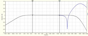
So I predict you'll obtain a different result from real playback of a sweep f test record, and only real playback will obtain the true transfer function of the generator loaded this way. So a test record is the only way, I think.
But good luck, and at least you'll have a working transimpedance MM/MI preamp.
PS: Attached is a simulation to illustrate. I predict you will obtain the blue trace, whereas playback will obtain the black trace.
LD
Attachments
Last edited:
Same here, gobs of putty here I come.
Enjoy the putty creations
George you're not differential.
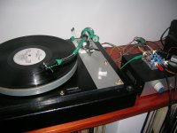
Yes Single-ended so far.
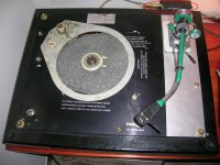
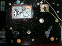
With the DL-103, I had the pre-pre at the back of the TT, 10 cm wiring.
Now with the MMs, the pre will be just by the base of the tonearm, in a recess of the TT chassis, 3 cm of external wiring, direct soldering, no connectors. The internal wiring of the SME arm is only 10pF.
But I haven’t abandoned the idea of a pre with the AD625.
And today while searching in the chaos, I discovered some antistatic bags with FETs inside.
Good luck.
Thank Hans and Lucky.
We discussed this previously, and topology differs from the real playback situation where the generator is intrinsic to the coil, and transimpedance input loading shunts self-capacitance of the coil and eliminates the resonance.
So I predict you'll obtain a different result from real playback of a sweep f test record, and only real playback will obtain the true transfer function of the generator loaded this way. So a test record is the only way, I think.
Lucky, let’s see how the low input impedance will affect the measurement.
My test records go only up to 20KHz unfortunately.
Question: If I play the test record at 45RPM, will the 20KHz increase to 27KHz [27=20*(45/33.3)] ?
George
Attachments
Low effective tonearm mass makes more of whatever suspension damping there is, in terms of lowering Q as well as raising resonant f.The kickstarter turntable I've been playing with has a very low mass tone arm does that explain the greater presence dip in my plot? I'm a little frustrated right now by the fact that changing to a Denon is outside of all its adjustment ranges.
So, if the thesis is true, you should expect a shallower but higher f mid dip.
Not sure how that fits your observations, Scott? Also, these things aren't very sensitive to changes in e-mass: sqrt law. Pretty much, the mid-dip is the mid-dip, and fairly well characterised as a shallow low Q dip of amplitude c 1-2dB max, often less, and sometimes not observable.
Putty is bad. Keep it in a separate locked room away from TTs, carts, pets, food, kids etc etc.....
LD
How do you measure a 1dB mid dip when your test record is at best +/-1dB?
Lazy question as I haven't yet found time to work this out for myself. Do we have a feel for the sort of noise performance the front end op-amp needs and are we optimising for current or voltage noise? This is for the parts box raiders who want to try it out.
Lazy question as I haven't yet found time to work this out for myself. Do we have a feel for the sort of noise performance the front end op-amp needs and are we optimising for current or voltage noise? This is for the parts box raiders who want to try it out.
Of course one couldn't be confident, in absolute terms. Nor would one worry, IMO, about such matters at the limit of audibility. As I say, it is a minor matter, but then so is extended audio bandwidth above the f limit of what is present in programme material on the record.How do you measure a 1dB mid dip when your test record is at best +/-1dB?
IMO the reason to look at the mid dip, which is probably real, is because it is a loose end, and understanding it might be revealing about the way the whole thing works. In this case, it might provide evidence of cantilever flex, for example, or it might contradict it.
I use Decca SXL2057 and the LXT mono version f band/sweep for most fine purposes, which has no spec tolerance AFAIK. However, it behaves as though it has a very well recorded flat response at least within +/- 1/2 dB IME, based on its use over a range of carts.
LD
- Home
- Source & Line
- Analogue Source
- mechanical resonance in MMs