Hei
Nice to hear you like the now long thread
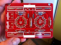
Nice board. Look like you got some quality components (compared to mine... Although those Philips caps are made 1999...
Extensions i should think is the problem actually. Have you soldered one groundcabel from - (minus) on philips cap to ground? Is volympot grounded? That caused me problem(s).
I would solder socket on back instead and have card mounted upside down with brass-spacers to get sockets to a good height.
/Johan
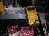
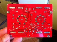
Those PSU filter caps are Rubycons. I think that they are good quality, +105C temperature rated, 220uF/450V. But I'm not sure of the manufacturing date. Output caps are made by Wima. Underside of pre amp PCB are small bypass caps for B+ and output caps. Also 470k resistors from output to ground.
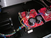
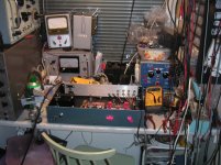
I have short and thick ground wire from PSU caps minus to back panel. That is only ground to chassis. Of course safety ground in IEC socket. Have a look on the pics. Volume pot is also grounded. I don't have any hum.
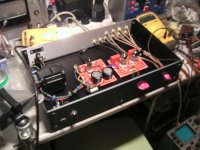
I need to tidy wiring a a little, and pay attention on some details, preamp is only 90% complete...
Can you elaborate a little what you mean by "I would solder socket on back instead and have card mounted upside down with brass-spacers to get sockets to a good height."
")
Attachments
Last edited:
Hei
Nice to hear you like the now long thread
Nice board. Look like you got some quality components (compared to mine... Although those Philips caps are made 1999...
Extensions i should think is the problem actually. Have you soldered one groundcabel from - (minus) on philips cap to ground? Is volympot grounded? That caused me problem(s).
I would solder socket on back instead and have card mounted upside down with brass-spacers to get sockets to a good height.
/Johan
Thanks Johan definitely do as advised.
For both Philips caps no they are not grounded. And will do so tonight.
For the volume pot how do I ground it?
Sorry when you say ground you meant Chassis ground or earth?
Thanks
Leon
Can you pls verify /clarify what and where is “high current grounds” and “socket safety ground”.
I like to visualize my grounds as water flowing to the sea.
-In this analogy the small signal grounds are the small feeder streams, which flow down to ;-
-The power supply caps and the speaker returns are the main rivers, which in turn flow down to :-
-The safety earth (the power supply socket ground) which is the sea itself.
As you can see the small delicate signal carrying points are furthest away from the sea where natural fluctuations (waves/tides) can have least impact.
If you think what would happen if you reversed the order with everything tied back to the small signal ground you the big current ripples would swamp the delicate signal and cause excessive hum and noise.
For me it just helps to visualize what is going on in a easily imagined way which takes the mystery out of what is a difficult to comprehend concept.
A single STAR grounding point - to which all grounds are tied, and which in turn is tied to the socket earth generally works equally as well in all but the most demanding situation.
Shoog
Fantastic, thanks and your analogy is worth a thousand words of explanation.
I am crystal clear now about the star ground principle.
Leon
Those PSU filter caps are Rubycons. I think that they are good quality, +105C temperature rated, 220uF/450V. But I'm not sure of the manufacturing date. Output caps are made by Wima. Underside of pre amp PCB are small bypass caps for B+ and output caps. Also 470k resistors from output to ground.
I have short and thick ground wire from PSU caps minus to back panel. That is only ground to chassis. Of course safety ground in IEC socket. Have a look on the pics. Volume pot is also grounded. I don't have any hum.
I need to tidy wiring a a little, and pay attention on some details, preamp is only 90% complete...
Can you elaborate a little what you mean by "I would solder socket on back instead and have card mounted upside down with brass-spacers to get sockets to a good height."
Hei Airhead
I'm sorry, i was talking to our new friend here Leon from Singapore. But thx alot for pics. Always nice.
Mä lähettä nyt viesti sulle
Soon this have to be official SRPP 6N3 thread =)
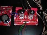
Airhead: Have your friend any thoughts of replacing those WIMA MKS on output? I think this SRPP needs something (much) better.
I think the biggest step in soundquality is those caps + tubes! Say to him to buy some russian 6n3p-eb... a really good tube. Then he can do a comparison again to Conrad Johnson =)
After 1-2 weeks i have a russian rectifier tube "over" (6X4-R) that fits your preamp without any modification. I'm currently using it but switching soon to 6x5GT. (almost new this 6X4-R)
If we meet up he can have it
Last edited:

Soon this have to be official SRPP 6N3 thread =)
Airhead: Have your friend any thoughts of replacing those WIMA MKS on output? I think this SRPP needs something (much) better.
I think the biggest step in soundquality is those caps + tubes! Say to him to buy some russian 6n3p-eb... a really good tube. Then he can do a comparison again to Conrad Johnson =)
After 1-2 weeks i have a russian rectifier tube "over" (6X4-R) that fits your preamp without any modification. I'm currently using it but switching soon to 6x5GT. (almost new this 6X4-R)
If we meet up he can have it
I let him know your recommendations.
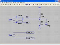
The circuit on post #24 is wrong, as the circuit on post#27
Try this
Thank you so much. I will try it tomorrow.
I suggested 330 Ω cathode resistors because it makes better results than 470 Ω in simulations and triodes work at about 70% of max limit dissipation, which is good for your valves.
If you decide a lower value that sounds better, be sure that not exceed max Wa=1.5 W
BTW, put a wire bridge instead of input capacitors, if you put a resistor, this is not the place for a grid stopper.
If you decide a lower value that sounds better, be sure that not exceed max Wa=1.5 W
BTW, put a wire bridge instead of input capacitors, if you put a resistor, this is not the place for a grid stopper.
Last edited:
I suggested 330 Ω cathode resistors because it makes better results than 470 Ω in simulations and triodes work at about 70% of max limit dissipation, which is good for your valves.
If you decide a lower value that sounds better, be sure that not exceed max Wa=1.5 W
BTW, put a wire bridge instead of input capacitors, if you put a resistor, this is not the place for a grid stopper.
I have 330R as cathode res now. But also, depending on voltage on B+ this have to be adjusted accordinaly. B+ is now 265V. Are you calculating this with the russain 6n3p in mind? The chinese 6n3 draw more current what i heard.
How do i calculate Wa?
The input caps have been removed for a while now. Gridstoppers are there instead now. Thats the right place right?
Didn't you see the updated schematic little earlier, post 254 and 253? (it was some mistake there as frank said)
On output there is instead of 1meg, 100K leakresistor.
thx
Johan
I have 330R as cathode res now. But also, depending on voltage on B+ this have to be adjusted accordinaly. B+ is now 265V. Are you calculating this with the russain 6n3p in mind? The chinese 6n3 draw more current what i heard.
I've made a simulation with a 6N3P model, and seems to me that 330 Ω is quite good.
How do i calculate Wa?
Measure the voltage drop in a cathode resistor, VRK, current is
ik = Vrk / Rk
Then
Wa ≈ (+B / 2) x ik
The input caps have been removed for a while now. Gridstoppers are there instead now. Thats the right place right?
No, the right place is as in your circuit on post#253, if your PCB follows the circuit on post#1 and #3, you hadn't grid stoppers at all.
That's the proof you don't need grid stoppers.
Didn't you see the updated schematic little earlier, post 254 and 253? (it was some mistake there as frank said)
The only mistake I can see in your circuit on post#253 is the volume pot, badly drawn.
On output there is instead of 1meg, 100K leakresistor.
thx
Johan
Anything between 100 K and 1 M is good.
Last edited:
Hi,
I was referring the 40 micro F caps right after the rectifier in the PSU which is 4 x higher than allowed.
BTW, don't the anodes of the EZ90 require some series resistance or is the DCR of the xformer high enough?
Also, if we were to replace the 50K ALPS pot with a 1M one then we could remove the 1M gridleak and the 330R gridstopper as well.
An input cap would be safer for a commercial unit but I guess it's O.K to omit it here.
Ciao,
The only mistake I can see in your circuit on post#253 is the volume pot, badly drawn.
I was referring the 40 micro F caps right after the rectifier in the PSU which is 4 x higher than allowed.
BTW, don't the anodes of the EZ90 require some series resistance or is the DCR of the xformer high enough?
Also, if we were to replace the 50K ALPS pot with a 1M one then we could remove the 1M gridleak and the 330R gridstopper as well.
An input cap would be safer for a commercial unit but I guess it's O.K to omit it here.
Ciao,
Last edited:
Hi,
I was referring the 40 micro F caps right after the rectifier in the PSU which is 4 x higher than allowed.
BTW, don't the anodes of the EZ90 require some series resistance or is the DCR of the xformer high enough?
Yes, you obviously was referring to the circuit on post#254.
I prefer regulated PSUs, and DC heaters supply, so I can't say much about it, only agree with you that 40 μF is too much.
Cap rolling in PSUs ?
Also, if we were to replace the 50K ALPS pot with a 1M one then we could remove the 1M gridleak and the 330R gridstopper as well.
An input cap would be safer for a commercial unit but I guess it's O.K to omit it here.
Ciao,
A 50 K volume pot is less noisy, I mean thermal noise, and volume pot is the dominant noise source here.
Hi,
I agree in theory. I do however doubt anyone would actually hear an increase in noise levels though.
No one's going to turn it up past 10 o'clock or do they?
Why not let the guinea pig(s) decide?
Ciao,
A 50 K volume pot is less noisy, I mean thermal noise, and volume pot is the dominant noise source here.
I agree in theory. I do however doubt anyone would actually hear an increase in noise levels though.
No one's going to turn it up past 10 o'clock or do they?
Why not let the guinea pig(s) decide?
Ciao,
Good for you, congratulations ! 
I assume you mean the resistive divider in PSU, you must put a cap there because you need +B/4 VDC, but 0 VAC and the cap does the trick.
As a final(?) advice, if AC heaters supply is a permanent choice, you must cut the tracks on your PCB and connect filaments directly on the socket pads, don't forget to twist the wires in order to minimize AC fields.
As a final(?) advice, if AC heaters supply is a permanent choice, you must cut the tracks on your PCB and connect filaments directly on the socket pads, don't forget to twist the wires in order to minimize AC fields.
Sorry, forget this, your PCB are double side and designed for DC heaters, a nightmare and a pity to cut the heater tracks.
If hum level is tolerable, let's PCB as it is.
Attachments

- Status
- This old topic is closed. If you want to reopen this topic, contact a moderator using the "Report Post" button.
- Home
- Amplifiers
- Tubes / Valves
- My first preamp with tubes